High-Resolution Imaging
Challenge
As PCBs and flat panel displays increase in density, the right camera is needed to design precise, cost-effective and high-throughput inspection systems.
Solution
Our high-resolution cameras are packed with features ideal for inspecting large and highly detailed parts. You can:
- Replace multiple cameras with a single 9, 12 or 20 MP camera.
- Increase throughput with advanced triggering at high frame rates.
- Capture highly detailed images with exceptional dynamic range and low noise.
High-Resolution Optical Inspection
Lowering costs by reducing complexity and increasing throughput
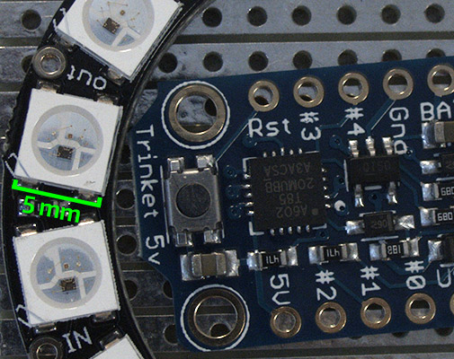
5 MP image shown at 100% magnification
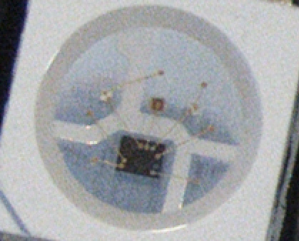
20 MP image shown at 100% magnification.
More detail can be detected inside the LED.
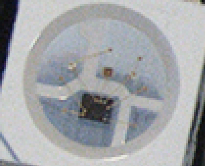
5 MP image shown at 400% magnification.
Detail inside the LED is more pixelated.
20 MP image shown only at 200% magnification. Cleaner detail is visible inside the LED.
Reduce Costs
An inspection system with several cameras requires multiple lenses, data cables, GPIO cables, and controller cards. A single ultra-high-resolution camera only needs one of each, adding up to huge savings. Using fewer parts also increases system reliability and reduces maintenance costs. The compact size of ultra-high-resolution 1” and 1.1” sensors allows them to be used with C-Mount optics. High-quality C-Mount lenses fully support ultra-high-resolution sensors, without the high cost and large size of F-Mount optics.
Simplify Your Inspection System
Compared to using multiple low-resolution cameras, a single ultra-high-resolution camera significantly reduces an imaging system’s complexity and cost. Using a single camera eliminates the need for multi-camera trigger synchronization and inspection artifacts caused by synchronization jitter. A single camera does not require channel bandwidth management, and provides greater freedom in lighting system design. With fewer cameras, lenses, cables, and interface cards, a single camera system is more reliable and much easier to calibrate and troubleshoot.
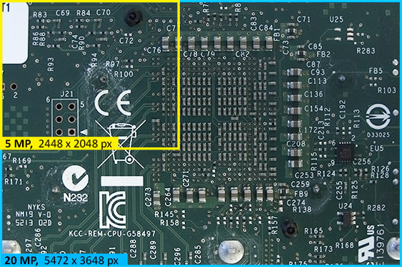
Left: Area covered by 4 x 5 MP cameras versus a single 20 MP camera.
Right: Proportional represenation of the area coverage difference based on 5 MP and 20 MP resolutions.
Using multiple cameras to cover a large area requires extremely precise alignment. Vibration and thermal expansion will result in “torn” images, where cameras fail to align correctly. Color imbalances between cameras introduce additional artifacts. Image alignment and color correction in software increases both the complexity of the vision application development process and the system resources required to run the application. Software alignment of a multi-camera system requires overlap between images and reduces the area covered. Calibrating one camera is quick and easy. Calibrating four cameras and ensuring that the calibration is maintained is far more time consuming. A single ultra-high-resolution camera allows you to avoid these issues.
High-Performance Camera Image Quality
For optical inspection of high-density PCBs and flat panel displays, pixel count alone isn’t enough. That’s why FLIR’s ultra-high-resolution cameras feature the latest Sony Pregius and Starvis sensors. Their exceptional imaging performance enables users to move beyond simple component position inspection to verification of part numbers, part orientation, and post-reflow joint quality.
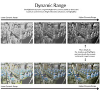
Dynamic Range
Dynamic range is the difference between the highest and lowest light intensities an image sensor can record. Sensors with a high dynamic range capture details in shadowed and brightly lit areas. When illuminated, the matte and highly reflective parts on a populated PCB produce shadows and bright highlights. A camera with a high dynamic range overcomes this without the need for multi-exposure HDR processing. Dynamic range is measured in dB.
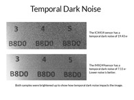
Temporal Dark Noise
Temporal dark noise, measured in e-, is the variance in the measurement of the brightness of a pixel as it is being read by the sensor. Temporal dark noise can cause pixels to appear bright, even when no photons have hit them. In dark areas like shadows or the surface of matte black ICs, temporal dark noise will result in a grainy image, making it difficult to see fine details like part numbers. Reducing temporal dark noise enables the detection of low intensity signals that would otherwise be hidden below the noise floor. The temporal dark noise of Sony Pregius and Starvis CMOS sensors is two-to-four times lower than that of other CMOS sensors, and four-to-nine times better than CCDs.
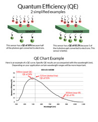
Quantum Efficiency
Quantum Efficiency (QE) is a measure of the camera’s sensitivity to light at specific wavelengths. The higher a sensor’s QE %, the more efficiently it can convert light into an electrical signal. The excellent QE of Sony’s latest 9MP, 12MP and 20MP sensors enables them to capture high-quality images with short exposures, minimizing inspection times.
For a more detailed explanation of QE, see Problem Solving #1: Capturing consistent color.
High-Throughput Inspection
The unique feature set of ultra-high-resolution FLIR cameras enables users to rapidly inspect large, highly detailed parts. High framerates and advanced triggering capabilities give users the precision control required to image flat panel displays in sync with their refresh cycles. The increased bandwidth of the 10 GigE interface supports even higher frame rates. The exceptional dynamic range of the latest CMOS sensors eliminates the need for multi-exposure HDR imaging, while their high QE and low temporal dark noise ensures that even short exposures capture excellent detail.
A Note About Lenses
To get the most from an ultra-high-resolution camera, you need high-resolution optics. High-quality lenses provide excellent brightness, contrast and sharpness across the entire image, not just in the center. While two lenses with the same focal length might look similar, their optical performance could differ greatly.
MTF charts
To help you select the correct lens for your camera and application, manufacturers will frequently show modular transfer function (MTF) charts in their lens specifications. MTF charts combine sharpness and contrast into the vertical axis, while the horizontal axis represents the distance from the center of the image. Higher performance lenses will have a higher MTF number, for a larger distance from the center of the lens.
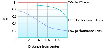
Left: Comparison chart of high-and-low-performance lenses to a hypothetical perfect lens.
The high-performance lens maintains excellent contrast and sharpness across the image.
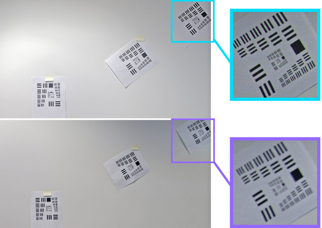
Right: Cropped details of the corners of images captured using a high-performance lens versus a standard lens. The greater contrast and sharpness is easily apparent. Lower performance lenses (purple) will loose clarity as you approach the corners and edges of the image.
Related Articles
-
 Deep Learning
Comparing Deep Learning Cameras with Smart Cameras
Read the Story -
 Embedded Vision
Guide for Integrating Board Level Cameras
Read the Story -
 USB3, GigE, 10GigE, and More
Interfaces for Machine Vision
Learn more