How do I work with alarms on the FLIR A310 using the digital output and input?
Requirements
- PC running Microsoft Windows 7 or higher
- FLIR IR Monitor 2.0.14
- FLIR IP Config 2.1
- FLIR A310, with:
-
- Power supply (P/N T910922)
- 12/24 V DC auxiliary power supply
- Ethernet cable
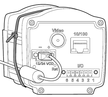
Cables and connections
Pin configuration
|
Pin |
Configuration |
Data |
|
1 |
IN 1 |
0–1.5V = low, 3–25 V = high, 200 mA |
|
2 |
IN 2 |
0–1.5V = low, 3 - 25 V = high, 200 mA |
|
3 |
OUT 1 |
ON = supply (max. 100 mA), OFF = open, 100 mA |
|
4 |
OUT 2 |
ON = supply (max. 100 mA), OFF = open, 100 mA |
|
5 |
I/O + |
6–24 V DC, max 200 mA |
|
6 |
I/O – |
Ground |
Description:
- IN 1: digital input 1 signal (+)
- IN 2: digital input 2 signal (+)
- OUT 1: digital output 1 signal (+)
- OUT 2: digital output 2 signal (+)
- I/O +: digital output power (+)
- I/O –: digital output/input power and signal (–)
Important: In order to use the digital output you must supply power to pins 5 and 6. The camera will not supply voltage to the the digital output when powered by its main power input or Power over Ethernet (PoE).
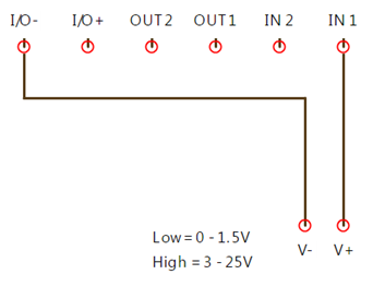
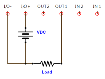
Digital input and output wiring
Digital input:
Digital output:
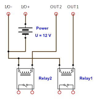
Using the camera as a dry contact
Some applications may require the camera to be used as a dry contact. In such cases, an auxiliary relay should be used, and the Relay# connector will be the dry contact.
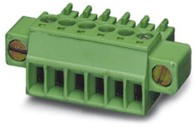
Specification—digital I/O connector
Digital I/O connector 1827745 MC 1,5/6-STF-3,81.
Plug components:
- Nominal current: 8 A.
- Rated voltage: 160 V.
- Pitch: 3.81 mm.
- Number of positions: 6.
- Type of connection: screw connection.
Working with alarms
General
You can make the camera trigger an alarm when certain conditions are met. An alarm can be triggered by several different sources, such as a measurement result in the image, a digital input, or an internal temperature sensor.
When an alarm is triggered, the camera can perform one or more tasks, e.g., save an image to memory, e-mail the image to predefined recipients, and send the image to an FTP site. The camera can also further trigger a variety of external devices, using the digital outputs.
Setting an alarm based on a measurement result
It is possible to configure alarms based on the temperature measurement results from the spot, box, and delta measurement tools. An alarm can also be configured for the internal temperature sensor, which can act as a thermometer for the ambient temperature.
To configure an alarm based on a measurement result, follow this procedure using FLIR IR Monitor:
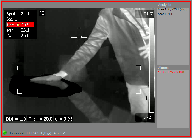
1. In the right pane, click the Alarms tab. Select an Alarm and double-click it. This displays a section where you can configure the alarm parameters and actions. Click the Measurement Alarm tab.
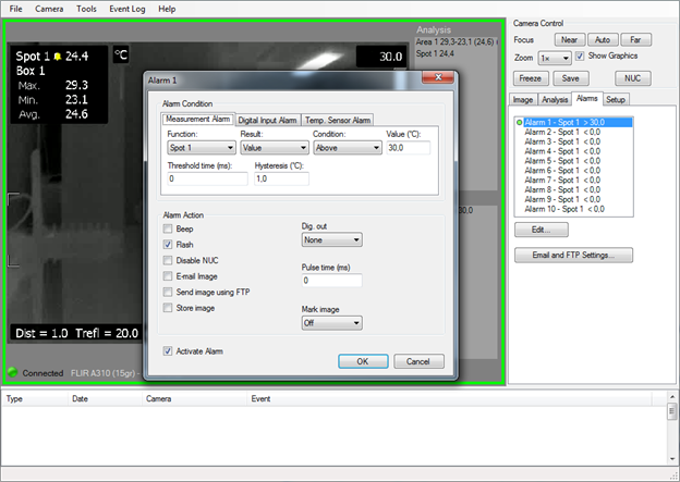
2. At the very bottom (left), check the option Activate Alarm to activate it.
3. In the Function list box, select the analysis tool that you want to use to trigger the alarm. The analysis tool must be one previously created.
4. In the Result list box, select the type of analysis result that you want to use to trigger the alarm. It may vary depending on the type of Function selected.
5. In the Condition list box, select the condition that triggers the alarm:
- Match: Triggers an alarm when the temperature matches the threshold value.
- Above: Triggers an alarm when the temperature is above the threshold value.
- Below: Triggers an alarm when the temperature is below the threshold value.
6. In the Value text box, enter the threshold temperature value to be used as the trigger limit.
7. In the Threshold time text box, enter the duration that must be matched or exceeded in order for the alarm to be triggered.
The duration specifies the amount of time that has to pass before an alarm is triggered. This can be used as a powerful tool to avoid false alarms.
8. In the Hysteresis text box, enter the hysteresis value.
Hysteresis is the interval within which the temperature value is allowed to vary without causing a change in the trigger. If the threshold is set above 30.0°C and the hysteresis is set at 2.0°C, the trigger goes high when the temperature rises above 30.0°C and stays high until the temperature drops below 28.0°C. In contrast, if the threshold is set below 30.0°C, and the same hysteresis value is kept, the trigger goes high if the temperature drops below 30.0°C and stays high until the temperature rises above 32.0°C.
9. Under Alarm Action, use the check boxes to select which actions the camera will perform when an alarm is triggered:
- Beep: Sets off an audio signal when an alarm is triggered.
- Flash: Displays a visible signal when an alarm is triggered.
- Disable NUC: Disables the automatic non-uniformity correction (NUC) when an alarm is triggered.
- E-mail image: Automatically sends the captured image to the recipients defined in Email and FTP Settings…. (Explanation not provided here.)
- Send image using FTP: Automatically sends the captured image to the FTP site defined in Email and FTP Settings…. (Explanation not provided here.)
- Store image: Saves the image frame that triggered the alarm.
10. In the Dig. out list box, select which digital output (None, 1 or 2) should send a digital pulse when the alarm is triggered.
11. If you have selected the alarm action Dig. out, enter the pulse length (in milliseconds) in the Pulse time text box. 0 = no pulse, constant high signal level on alarm.
12. In the Mark Image list box, select which tag should be inserted in the image stream. The choices are Start, Stop, and Tag.
13. When completed, click OK.
Setting an alarm based on the digital input
It is possible to set an alarm based on the digital input.
To configure an alarm based on the digital input, follow this procedure using FLIR IR Monitor:
1. In the right-hand pane, click the Alarms tab. Select an Alarm and double-click it. This displays a section where you can configure the alarm parameters and actions. Click the Digital Input Alarm tab.

2. At the very bottom (left), check the option Activate Alarm to activate it.
3. In the High voltage trigger check box:
- When selected, the camera is set to react to a high digital-in signal.
- When cleared, the camera is set to react to a low digital-in signal.
4. In the Input box list, select the digital input associated to the alarm, 1 or 2.
5. Under Alarm Action, use the check boxes to select which actions the camera will perform when an alarm is triggered:
- Beep: Sets off an audio signal when an alarm is triggered.
- Flash: Displays a visible signal when an alarm is triggered.
- Disable NUC: Disables the automatic NUC when an alarm is triggered.
- E-mail image: Automatically sends the captured image to the recipients defined in Email and FTP Settings…. (Explanation not provided here.)
- Send image using FTP: Automatically sends the captured image to the FTP site defined in Email and FTP Settings…. (Explanation not provided here.)
- Store image: Saves the image frame that triggered the alarm.
6. In the Dig. out list box, select which digital output (None, 1 or 2) should send a digital pulse when the alarm is triggered.
7. If you have selected the alarm action Dig. out, enter the pulse length (in milliseconds) in the Pulse time text box. 0 = no pulse, constant high signal level on alarm.
8. In the Mark Image list box, select which tag should be inserted in the image stream. The choices are Start, Stop, and Tag.
9. When completed, click OK.
Setting an alarm for when the camera or the digital output cable fails
The FLIR A310 does not support setting the digital output to normally closed, so in order to have an alarm in case the camera fails, reverse alarm logic is used.
See the "Setting an alarm based on a measurement result" section above to configure the alarm on the camera. A fire detection example will be used to illustrate the application.
Usually, to set an early fire alarm, the max temperature of a measurement box is used to set the alarm, the Condition is set to Above, and Threshold is set to an elevated temperature, such as 100°C (212°F). With this configuration, if the maxtemperature of a given measurement box exceeds Threshold value (100°C (212°F)), the camera digital output will be set to active.
Straight logic:
- Alarm: box max temperature
- Condition: Above
- Threshold: 100°C
- Pulse time: 0
- Digital output normal status: not active (e.g., 0 V DC)
- Digital output alarm status: active (e.g., 12 V DC)
Using straight logic, if the camera fails there is no way to detect the failure by the digital output status, which will be active only if there is an active alarm condition.
Reverse logic is based on the alarm condition being the lack of an alarm. So, instead of setting the alarm Condition to Above, it will be set to Below. The natural condition of the alarm will be "active," and when the max temperature of the box exceeds the Threshold value, the alarm will be deactivated
Reverse logic:
- Alarm: box max temperature
- Condition: Below
- Threshold: 100°C
- Pulse time: 0
- Digital output normal status: active (e.g., 12 V DC)
- Digital output alarm status: not active (e.g., 0 V DC)
Using reverse logic, the digital output status will be active during normal camera operation and will be deactivated when an alarm condition is present. Reverse logic combined with an auxiliary relay (when NC is used) will give a high signal when there is an alarm, when the camera fails, or when the digital output cable fails. See "Using the camera as a dry contact" above as a reference.
Working with measurement masks
A measurement mask is a manually created free-form area within a fixed measurement area that can be used when working with alarms. For example, if you create a rectangular area but only want an alarm to trigger if conditions are met in a smaller, irregularly shaped area inside the rectangular area, use a measurement mask to achieve this.
Follow this procedure:
1. Click the Analysis tab and select the Use Measurement Mask check box.
2. Click Measurement Mask… This will display the Measurement Mask dialog box.
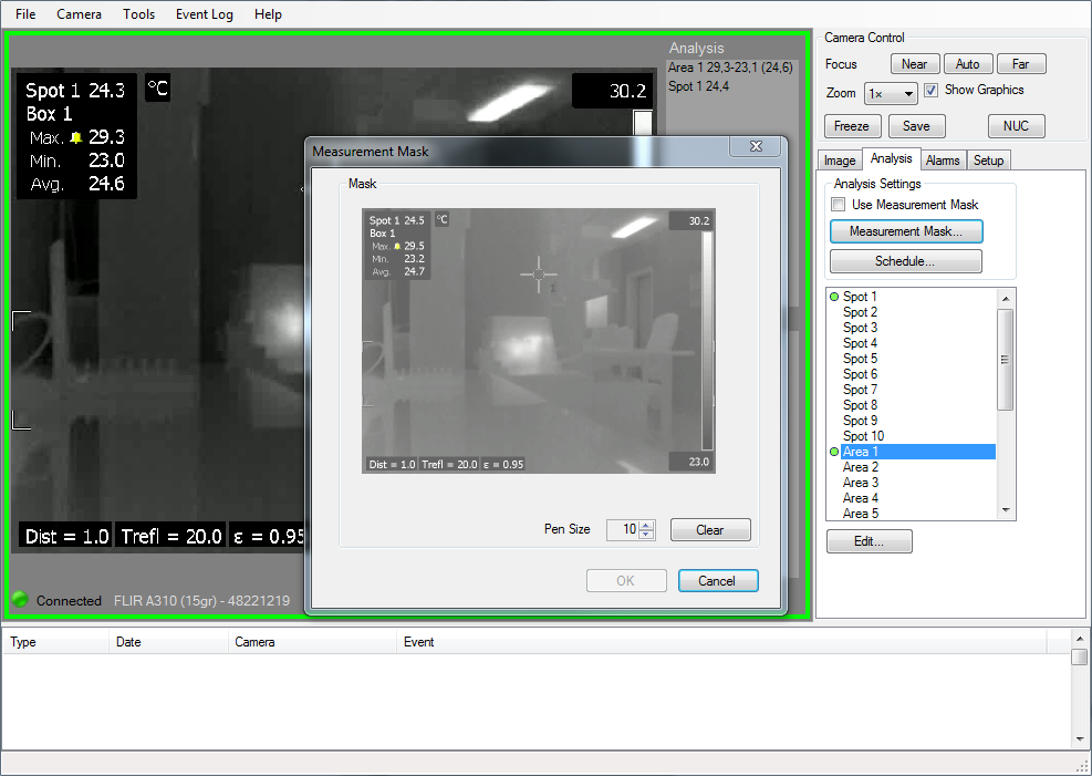
3. In the Measurement Mask dialog box, select a Pen Size (in pixels) and use the cursor to paint a free-form area within the measurement area (box) that you previously created.
4. To leave the dialog box and apply the mask to the selected camera, click OK.
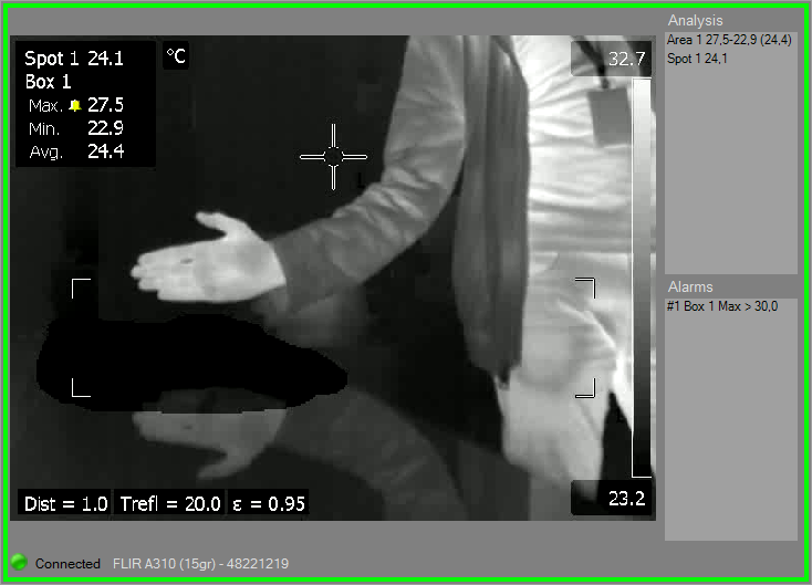
5. Once the Use Measurement Mask is selected the only valid area for the alarm will be the masked inside the measurement area (box). So even if there is an alarm condition inside the measurement box, it will not activate the alarm if the condition is not inside the masked area. The following screenshots show the use of a measurement mask inside a measurement area.
Related Articles
-
 Application Story
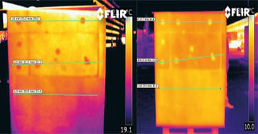
FLIR cameras support analysis and diagnosis of external thermal insulation systems
Read the Story -
 Case Study
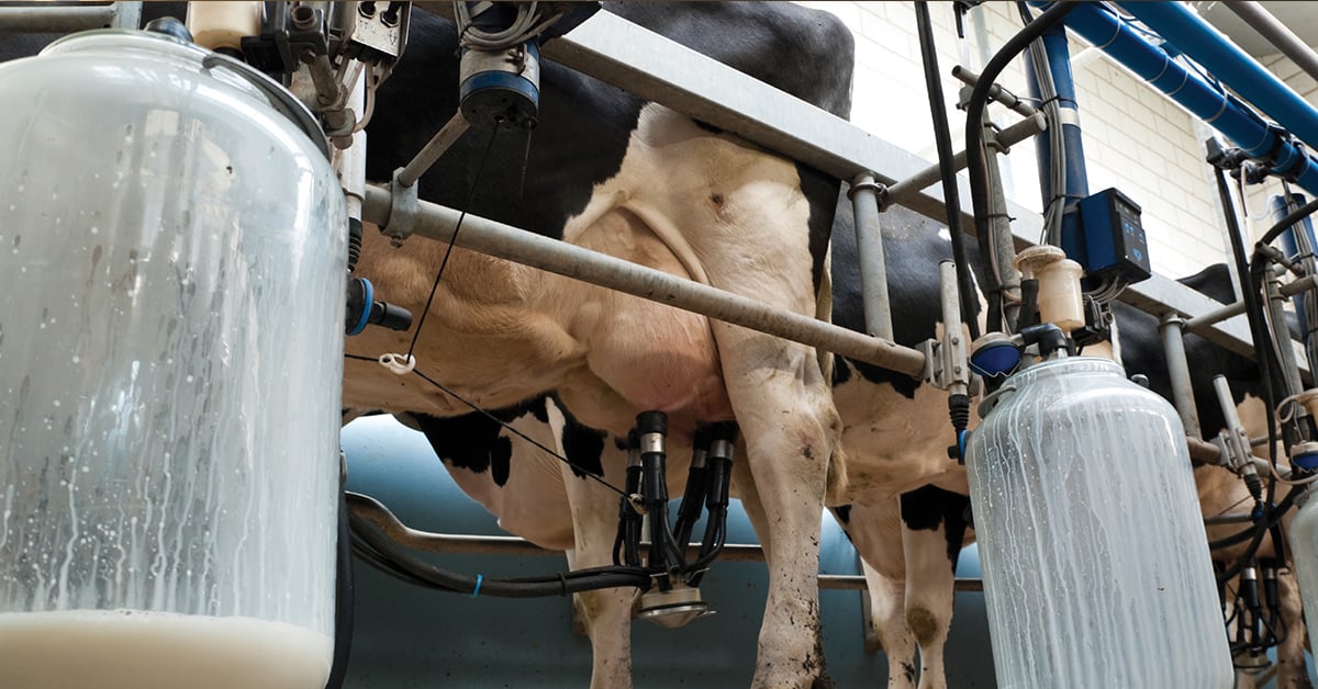
Automatic Health Check in Dairy Farms Using FLIR Thermal Imaging Cameras
Read the Story -
 Deep Learning
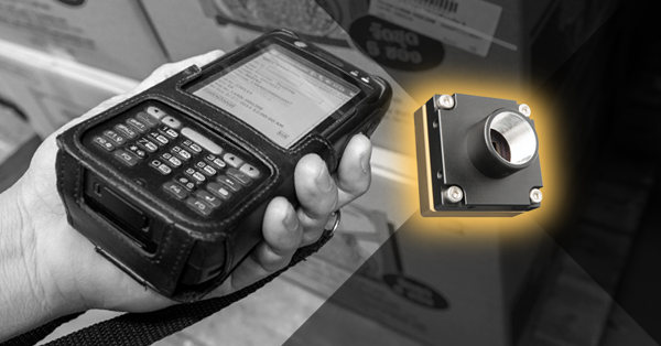
Comparing Deep Learning Cameras with Smart Cameras
Read the Story