Setting Up Multiple USB 3.1 Cameras
Download PDF - USB3-Multiple-Camera
Preparing for Use
Before you use your USB 3.1 camera, we recommend that you are aware of the following resources available from our Downloads page:
Getting Started Manual for the camera—provides information on installing components and software needed to run the camera.
Technical Reference for the camera—provides information on the camera’s specifications, features and operations, as well as imaging and acquisition controls.
Firmware updates—ensure you are using to most up-to-date firmware for the camera to take advantage of improvements and fixes.
Spinnaker SDK—(for Blackfly S cameras only) contains all documentation, example source code, precompiled examples, and libraries required to develop your application using our Spinnaker SDK.
FlyCapture2 SDK—contains utilities to configure the camera such as Driver Control GUI, update firmware and drivers, and check setup. As well, contains the FlyCapture2 API for use in creating your own applications.
Overview
When choosing to do a multi-camera system setup, there are a number of parameters necessary to review to ensure a successful setup. Specifically:
- Using multiple usb3 host adapters or a hub will determine the overall bandwidth limitation seen by a camera. Using multiple host adapters means each host adapter provides full interface bandwidth; using hubs/switches may limit total camera bandwidth to the interface bandwidth limit, but they can also be used universally by desktop, laptop and embedded system devices.
- DeviceLinkThroughputLimit is a camera setting that determines the total bandwidth each camera can take up. When using multiple cameras on one bus/host adapter, it is important to reduce this to ensure that the combined bandwidth of all of the cameras do not exceed the bandwidth limitations of the interface, while maintaining a certain value to achieve your application required resolution/framerate combination.
- System Components are important to determine the processing performance of a computer/host system. It's important to know the specifications necessary to run multiple cameras, and what kind of performance you cna expect for a given hardware system.
This article provides details on system setups we have tested using multiple cameras, the camera settings used to achieve that bandwidth, and things to look out for when configuring your own multi-camera system.
Configure Drivers
We sell three USB 3.1 host controller cards: two based on the FL1100 chipset from Fresco and the µPD720200 chipset from Renesas. In addition to the manufacturer drivers, we recommend using the PGRUSBCam driver. For a list of compatible chipsets, see Recommended USB 3.1 System Components.
With SpinView (for Blackfly S) or our driver control utility, you are able to identify the driver you are using and easily switch between them. Select the Point Grey Driver from the driver selection window.
Bandwidth Allocation
USB 3.1 does not automatically manage bandwidth allocation. To help users accommodate multiple cameras on a single bus, we use a camera attribute which limits peak data bandwidth. This can be used to reduce the amount of data coming from each camera, preventing skipped frames or connectivity issues. When factoring in the related overhead, the effective max bandwidth for USB 3.1 is approximately 450MB/s.
Device Link Throughtput Limit-GenICam
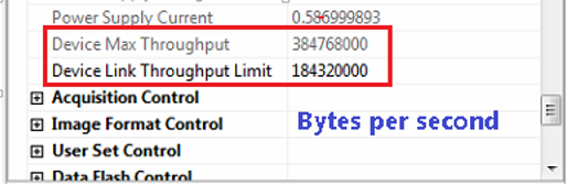
Use the device throughput limit feature to verify your system’s bandwidth limit, ensure your total bandwidth use is within that limit, and adjust your camera’s bandwidth accordingly. Consider the total of all the cameras on the system to calculate the required bandwidth.
We recommend that the bandwidth requirements be divided equally among the number of cameras used, for example—two cameras, each requiring half of the maximum bandwidth; three cameras, each requiring one third of the maximum bandwidth.
In the figure below, we see that the device max throughput is 38768000 bytes per second (384 MB/s). The current device link throughput limit is 18320000 bytes per second (184 MB/s).
Format 7 Packet Size-IIDC
Format 7 packet size provides the user with a mechanism to allocate bandwidth for a particular camera. Reducing the packet size lowers the camera’s maximum frame rate and limits the amount of bandwidth the camera can use. The packet size can be controlled in FlyCapture2 or the IIDC registers.
FlyCap2 can be used to determine the bandwidth allocated for a given packet size. Reduce or increase the packet size to ensure the total amount of bandwidth output by the camera(s) does not exceed system limits.
In the figure below, we see that reducing the packet size to 22624 bytes limits the maximum frame rate to 55 FPS, assuming image size and pixel format stay the same.

Calculating Required Bandwidth
To calculate your bandwidth requirements, use your required resolution, frame rate, and pixel format (bytes per pixel) in the following equation.
Height x Width x Frame Rate x Bytes per Pixel = Bandwidth in MB
For example:
Camera model: FL3-U3-13S2M-CS
Resolution: 1328 x 1048
Frame rate: 60 FPS
Pixel format: Mono16
Bandwidth = 1328 x 1048 x 60 x 2 = 167 MB
|
Pixel format |
Mono8/Raw8 |
Mono12/Raw12 |
Mono16/Raw16 |
RGB8 |
YUV411 |
YUV422 |
YUV444 |
|
Bytes per pixel |
1 |
1.5 |
2 |
3 |
1.5 |
2 |
3 |
Multiple camera system configurations
This section documents various configurations and scenarios that have been tested with our USB 3.1 multiple cameras. The hardware and software setup with each configuration is also documented.
Multiple cameras connected directly to a USB 3.1 host controller
The figure below illustrates 4 cameras running on a 4 port USB3 card with Fresco FL1100 host controller.
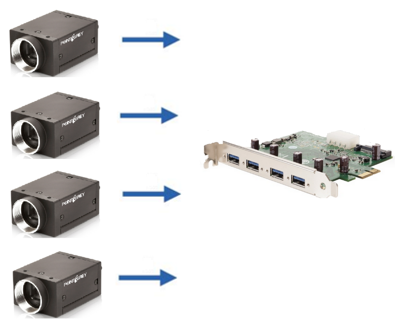
Multiple cameras connected directly to the host controller
System Description
|
Component |
Description |
|
CPU |
Intel Core i-7 4790 |
|
Motherboard |
Asus Z97-PRO |
|
RAM |
8 GB |
|
Host adapter |
FLIR 4 Port USB 3.1 PCI Host Adapter (ACC-01-1202) |
|
Cabling |
FLIR 3-meter USB 3.1 Cable Type-A to Micro-B |
|
Operating system |
Windows 7 x64 |
|
Driver |
PGRUSBCam Driver 2.7.3.18 |
|
Software |
Test application based on FlyCapture2 Release 2.7.3.13 x64 |
|
Camera |
|
|
Camera firmware |
2.11.3.0 |
We used a console test application to obtain the test result below. The test application configures each camera to run at high performance mode and verifies that there are no dropped images.
|
Camera Model |
Pixel Format |
Resolution |
Frame Rate |
Packet Size (Byte) |
Bandwidth (MB/s) |
|
GS3-U3-23S6M-C |
Raw8 |
1920 x 1200 |
40 |
33120 |
92 |
|
GS3-U3-23S6M-C |
Raw8 |
1920 x 1200 |
40 |
33120 |
92 |
|
GS3-U3-23S6C-C |
Raw8 |
1920 x 1200 |
40 |
33120 |
92 |
|
GS3-U3-23S6C-C |
Raw8 |
1920 x 1200 |
40 |
33120 |
92 |
|
Total bandwidth |
|
|
|
|
368 MB/s |
Using the configuration above, a total of 368 MB/s is transferred to the host from multiple cameras. Although the effective USB 3.1 bandwidth is approximately 450 MB/s, peak performance can vary, depending on how the USB3 host adapter card manages bandwidth.
Multiple cameras connected via a USB 3.1 hub
This configuration demonstrates free-running 2 and 3 cameras using a single USB 3.1 hub. A table is provided to demonstrate the frame rates achieved in each configuration. As shown from the results, the USB 3.1 hub used could not sustain a data rate of greater than 345 MB/s.
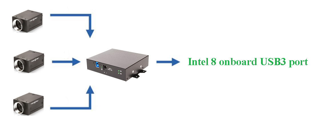
Multiple cameras connected to the host via hub
System Description
|
Component |
Description |
|
CPU |
Intel Core i-7 4770 |
|
Motherboard |
ASUS Z87-PRO |
|
RAM |
8 GB |
|
Host adapter |
Onboard Intel USB 3.1 port |
|
Hub |
4-Port USB 3.1 Hub with Screw Locks and External Power Adapter (ACC-01-6000) |
|
Cabling |
FLIR 3-meter USB 3.1 Cable Type-A to Micro-B |
|
Operating system |
Windows 7 x64 |
|
Driver |
PGRUSBCam Driver 2.7.3.18 |
|
Software |
Test application based on FlyCapture2 Release 2.7.3.13 x64 |
|
Camera |
|
|
Camera firmware |
2.11.3.0 |
Note: For further recommendations, see Recommended USB 3.1 System Components.
Example A - One camera connected to a hub
|
Camera model |
Pixel Format |
Resolution |
Frame Rate |
Packet Size (Byte) |
Bandwidth (MB/s) |
|
GS3-U3-23S6M |
Raw8 |
1920 x 1200 |
162 |
48096 |
373 |
|
Total bandwidth |
|
|
|
|
373 MB/s |
Example B - Two cameras connected to a hub
|
Camera model |
Pixel Format |
Resolution |
Frame Rate |
Packet Size (Byte) |
Bandwidth (MB/s) |
|
GS3-U3-23S6M |
Raw8 |
1920 x 1200 |
70 |
48096 |
161 |
|
GS3-U3-23S6M |
Raw8 |
1920 x 1200 |
70 |
48096 |
161 |
|
Total bandwidth |
|
|
|
|
322 MB/s |
Example C – Three cameras connected to a hub
|
Camera |
Pixel Format |
Resolution |
Frame Rate |
Packet Size (Byte) |
Bandwidth (MB/s) |
|
GS3-U3-23S6M |
Raw8 |
1920 x 1200 |
50 |
48096 |
115 |
|
GS3-U3-23S6M |
Raw8 |
1920 x 1200 |
50 |
48096 |
115 |
|
GS3-U3-23S6M |
Raw8 |
1920 x 1200 |
50 |
48096 |
115 |
|
Total |
|
|
|
|
345 MB/s |
Using the configurations above, the total throughput ranges from 322 MB/s to 373 MB/s. Although the effective USB 3.1 bandwidth is approximately 450 MB/s, peak performance can vary depending on how the USB 3.1 host controller manages bandwidth.
Multiple Cameras Connected to Multiple Host Controllers
The following configuration uses multiple host controllers to share the bandwidth for 15 cameras.
System Description
| Component | Description |
|---|---|
|
CPU |
Intel i7 4790 @ 3.8 GHz |
|
Motherboard |
ASUS Z97 Pro |
|
RAM |
8 GB 1333 MHz non-ECC memory |
| Hard Drive | 500 GB Segate - 7200 RPM |
| Power Supply | 500 W Thermtake PSU |
|
Host Adaptor |
2 x onboard Intel 9 series USB3 ports |
|
Host Adaptor Driver |
Intel USB3.0 eXtensible Host Controller version 4.0.0.36 |
|
Cabling |
15 x FLIR 3-meter USB 3.1 Cable Type-A to Micro-B (ACC-01-2300) |
|
Operating system |
Windows 7 x64 |
|
Driver |
PGRUSBCam Driver 2.7.3.18 |
|
Software |
Test application based on FlyCapture2 Release 2.8.3.1 x64 |
|
Camera |
15 x Grasshopper®3 USB3 |
|
Camera firmware |
See test results |
System Description
| Camera Model | Pixel Format | Resolution | Frame Rate | Firmware | Bandwidth (MB/s) |
|---|---|---|---|---|---|
|
GS3-U3-120S6M |
Mono8 |
640 x 480 |
30 |
1.17.2.0 |
9 |
|
GS3-U3-120S6M |
Mono8 |
1288 x 968 |
17 |
2.22.3.0 |
21 |
|
GS3-U3-120S6M |
Mono8 |
1288 x 968 |
21 |
2.22.3.0 |
64 |
|
GS3-U3-120S6M |
Mono8 |
1280 x 968 |
25 |
2.22.3.0 |
17 |
|
GS3-U3-91S6C |
Raw8 |
1288 x 968 |
17 |
2.22.3.0 |
21 |
|
GS3-U3-91S6C |
Raw8 |
1288 x 968 |
17 |
2.22.3.0 |
21 |
|
GS3-U3-91S6C |
Raw8 |
1288 x 968 |
17 |
2.22.3.0 |
21 |
|
GS3-U3-91S6C |
Raw8 |
1384 x 1032 |
45 |
2.22.3.0 |
64 |
|
GS3-U3-60QS6C |
Raw8 |
1288 x 968 |
27 |
2.22.3.0 |
34 |
|
GS3-U3-41C6M |
Mono8 |
640 x 480 |
188 |
2.22.3.0 |
233 |
|
GS3-U3-41C6C |
Raw8 |
1280 x 968 |
188 |
2.22.3.0 |
233 |
|
GS3-U3-41C6M |
Mono8 |
1280 x 968 |
188 |
2.22.3.0 |
233 |
|
GS3-U3-41S4M |
Mono8 |
1288 x 968 |
29 |
2.22.3.0 |
36 |
|
GS3-U3-41S4M |
Mono8 |
1288 x 968 |
29 |
2.7.3.0 |
36 |
|
GS3-U3-15S5C |
Raw8 |
1384 x1032 |
45 |
2.22.3.0 |
64 |
|
Total bandwidth |
|
|
|
|
1137 MB/s* |
*Bandwidth shared across multiple host controllers
Troubleshooting
Enumeration
- When using a USB 3.1 camera, ensure it is adequately powered by an external adapter.
- Ensure the latest firmware and drivers are being used.
Link Recovery Errors
- The host controller enters a recovery state to recover from bit errors that it has detected. This is often caused by a long cable or a bad connection.
- Use the same cables to ensure the performance of each camera is consistent. Shorter cables are also preferred for better reliability.
- For more information, see Diagnosing USB 3.1 Camera and Bus Errors.
Skipped Image Frames
- This happens when the host is too slow in receiving and acknowledging the data coming from the camera. It can be caused by a host system that is too busy or by having too much data on the USB 3.1 bus for the host to handle.
- To view the number of skipped frames:
- In SpinView, see the Log Viewer.
- In FlyCapture2, see the Camera Information panel.
- To alleviate the issue, manually reduce the Format 7 packet size until the max fram rate is reduced and images are no longer being skipped.
- Using a higher performance PC also ensures fewer frames are skipped.
Low Frame Rate
- To increase the frame rate:
- In SpinView, increase the Device Link Throughput Limit.
- In FlyCapture 2, increase the Format 7 packet size.
- Increase the Format 7 packet size.
- Ensure the PCI Express bus is 2.0 compliant. If a PCI Express 1.0 bus is used, the effective bandwidth (and hence frame rate) will be reduced by half.
- Ensure images frames are not being skipped. Please refer to the Skipped Image Frames section for more information.
- For more information, see KB 10108 My USB 3.1 camera does not achieve full frame rate.