Using Logic Blocks
Application Note Description
This document provides an overview of the Logic Block Control feature.
Introduction
A logic block is a collection of combinatorial logic and latches that allows you to create new, custom signals inside the camera. These custom signals can be used by the camera (for example to trigger exposure) or sent out to integrate with external systems.
Some applications of this are:
- Trigger Latch—to detect missing triggers and refire
- Trigger Mode—to create your own custom trigger modes
The camera has two logic blocks available for configuration.
This application note provides three examples of logic block configuration:
Example—Self-Start Trigger Mode
Example—Custom Trigger Mode
Example—Trigger Latch
Overview of Logic Block Control
Each camera has two logic blocks available. Each logic block is comprised of two lookup tables (LUT) with configurable inputs, truth tables and a flip flop output.
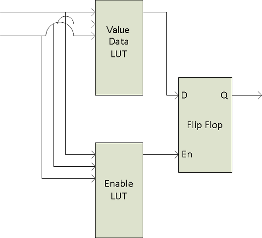
The two LUTs are: the Value Data LUT (D) and the Enable LUT (EN). When combined together in a flip flop, they provide three outputs [Q (next)]: 0, 1, or Q (previous). Q (previous) uses the last Q (next) value.
| Value LUT | Enable LUT | Output |
|---|---|---|
| D | EN | Q (next) |
| 0 | 0 | Q (previous) |
| 0 | 1 | 0 |
| 1 | 0 | Q (previous) |
| 1 | 1 | 1 |
When the Enable LUT is 0 the output is always Q (previous). When the Enable LUT is 1 the output is equal to the Value LUT.
Both of these LUTs share up to three inputs and have eight states for their truth table. Using the combination the three inputs, you can determine the output.
Configuring Logic Blocks
Step 1—Determine your inputs
Each logic block starts with a table as per below, with three available inputs and the sequence from 0,0,0 to 1,1,1.
| Row | Input 2 | Input 1 | Input 0 | Logic Block Output |
|---|---|---|---|---|
| 0 | 0 | 0 | 0 | |
| 1 | 0 | 0 | 1 | |
| 2 | 0 | 1 | 0 | |
| 3 | 0 | 1 | 1 | |
| 4 | 1 | 0 | 0 | |
| 5 | 1 | 0 | 1 | |
| 6 | 1 | 1 | 0 | |
| 7 | 1 | 1 | 1 | |
The possible inputs include:
- Zero—No input; this is a constant signal at level low
- Line 0/2/3—GPIO 0/2/3 external hardware trigger
- User Output 0/1/2/3—User defined signal (controlled by software only)
- Counter 0/1 Start—When the Counter signal is activated
- Counter 0/1 End—When the Counter signal is completed
- Logic Block 0/1—Output of one of the two logic blocks
- Exposure Start—When the sensor starts capturing an image
- Exposure End—When the sensor stops capturing an image
- Frame Trigger Wait—When the camera is ready to capture an image (i.e., not exposing or transferring data)
- Acquisition Active—When the camera is capturing an image
As the output of one logic block (LB0) can be used as the input of the second logic block (LB1), you can potentially use five different inputs when combining them together.
Step 2—Determine your input activation types
In the past, a trigger could only have one source at any given time, allowing the camera to be triggered by either a rising edge or a falling edge. Now high and low signals can be viewed as events creating five states: level low, rising edge, level high, falling edge, and any edge.
Which activation type to use is dependent on the input chosen and the desired outcome. In some cases it may be necessary to know the waveform of the input signal.
Step 3—Determine your logic block output values
The desired output is based on the input values or combination of input values. Output values are 0, 1, or Q (previous).
| Row | Input 2 | Input 1 | Input 0 | Logic Block Output |
|---|---|---|---|---|
| 0 | 0 | 0 | 0 | |
| 1 | 0 | 0 | 1 | |
| 2 | 0 | 1 | 0 | |
| 3 | 0 | 1 | 1 | |
| 4 | 1 | 0 | 0 | |
| 5 | 1 | 0 | 1 | |
| 6 | 1 | 1 | 0 | |
| 7 | 1 | 1 | 1 |
Step 4—Determine your Value LUT and Enable LUT values
The values for the LUTs are based on the output table (shown below) and the desired output values determined in step 3.
| Output Table | ||
|---|---|---|
| Value LUT | Enable LUT | Logic Block Output |
| D | EN | Q (next) |
| 0 | 0 | Q (previous) |
| 0 | 1 | 0 |
| 1 | 0 | Q (previous) |
| 1 | 1 | 1 |
Complete the Logic Block table with the Value and Enable LUT data.
| Row | Input 2 | Input 1 | Input 0 | Value LUT |
Enable LUT |
Logic Block Output |
|---|---|---|---|---|---|---|
| 0 | 0 | 0 | 0 | |||
| 1 | 0 | 0 | 1 | |||
| 2 | 0 | 1 | 0 | |||
| 3 | 0 | 1 | 1 | |||
| 4 | 1 | 0 | 0 | |||
| 5 | 1 | 0 | 1 | |||
| 6 | 1 | 1 | 0 | |||
| 7 | 1 | 1 | 1 |
Step 5—Translate the Value and Enable LUTs into Hex
By using Hex, you can define the Value and Enable LUTs as one entry each, rather than row by row.
| Row | 7 | 6 | 5 | 4 | 3 | 2 | 1 | 0 | Hex |
|---|---|---|---|---|---|---|---|---|---|
| Value | |||||||||
| Enable |
Step 6—Enter the Values in SpinView to Test and Confirm Configuration
The SpinView application is a generic, easy-to-use streaming image viewer included with the Spinnaker SDK that can be used to test many of the capabilities of your Point Grey camera. It provides access to the features of the camera for configuring and testing purposes.


Example 1—Self-Start Trigger Mode
This example shows how to configure a logic block to trigger the camera whenever it is ready to be triggered. The outcome of this example is similar to when the Trigger Selector is set to Acquisition Start.
Step 1—Determine your Inputs
For this example, only one input is used: Frame Trigger Wait (FTW). The FTW signal is 1 when the camera is ready to be triggered and 0 when it is not. Input 1 and Input 2 are not required, so they can be ignored.
| Row | Input 2 | Input 1 | Input 0 FTW |
Value LUT |
Enable LUT |
LB0 Output |
|---|---|---|---|---|---|---|
| 0 | 0 | 0 | 0 | |||
| 1 | 0 | 0 | 1 | |||
| 2 | 0 | 1 | 0 | |||
| 3 | 0 | 1 | 1 | |||
| 4 | 1 | 0 | 0 | |||
| 5 | 1 | 0 | 1 | |||
| 6 | 1 | 1 | 0 | |||
| 7 | 1 | 1 | 1 |
Step 2—Determine your Input Activation Types
The activation type for FTW in this example is Level High.
Step 3—Determine your LB0 Output
Since only one input (FTW) is used the LB0 output mirrors this source. LB0 outputs 1 to the trigger, triggering the camera when it is ready.
| Row | Input 2 | Input 1 | Input 0 FTW |
Value (D) LUT |
Enable (EN) LUT |
LB0 Output |
|---|---|---|---|---|---|---|
| 0 | 0 | 0 | 0 | 0 | ||
| 1 | 0 | 0 | 1 | 1 | ||
| 2 | 0 | 1 | 0 | 0 | ||
| 3 | 0 | 1 | 1 | 1 | ||
| 4 | 1 | 0 | 0 | 0 | ||
| 5 | 1 | 0 | 1 | 1 | ||
| 6 | 1 | 1 | 0 | 0 | ||
| 7 | 1 | 1 | 1 | 1 |
Step 4—Determine your Value LUT and Enable LUT
Since the LB0 output is always either a 0 or a 1 [and not a Q (previous)] the Enable LUT is always 1.
| D | EN | LB0 Output |
|---|---|---|
| 0 | 0 | Q (previous) |
| 0 | 1 | 0 |
| 1 | 0 | Q (previous) |
| 1 | 1 | 1 |
Knowing the LB0 output and the Enable LUT the Value LUT can be determined. In this case, as the Enable LUT is always 1, the Value LUT mirrors the LB0 Output.
| Row | Input 0 FTW |
Value (D) LUT |
Enable (EN) LUT |
LB0 Output |
|---|---|---|---|---|
| 0 | 0 | 0 | 1 | 0 |
| 1 | 1 | 1 | 1 | 1 |
| 2 | 0 | 0 | 1 | 0 |
| 3 | 1 | 1 | 1 | 1 |
| 4 | 0 | 0 | 1 | 0 |
| 5 | 1 | 1 | 1 | 1 |
| 6 | 0 | 0 | 1 | 0 |
| 7 | 1 | 1 | 1 | 1 |
Step 5—Translate the Value and Enable LUTs into Hex
| Row | 7 | 6 | 5 | 4 | 3 | 2 | 1 | 0 | Hex |
|---|---|---|---|---|---|---|---|---|---|
| Value | 1 | 0 | 1 | 0 | 1 | 0 | 1 | 0 | 0xAA |
| Enable | 1 | 1 | 1 | 1 | 1 | 1 | 1 | 1 | 0xFF |
Step 6—Enter the Values in SpinView to Test and Confirm Configuration
1. In SpinView, on the Logic Block Control feature tree:
- Select Logic Block 0.
- Select Logic Block LUT Enable.
- Enter the Output Value All: 0xFF.
- Select the Logic Block LUT Input 0, Frame Trigger Wait, and Level High.
- Select Logic Block LUT Value.
- Enter the Output Value All: 0xAA.

2. On the Acquisition Control feature tree:
- Select Frame Start as the Trigger Selector.
- Set Trigger Mode to On.
- Select Trigger Source Logic Block 0.
- Select Trigger Activation Level High.

Example 2—Custom Trigger Mode
This example shows how to create a custom trigger mode. When in use, even if the camera is receiving trigger pulses it only triggers under a second condition; for example, only after a certain amount of time.
Step 1—Determine your Inputs
There are two inputs:
- Trigger Pulse (Line 0)—when the camera is triggered externally via a trigger pulse
- User Output 0—a user-controlled value
As only two inputs are used, Input 2 can be ignored.
| Row | Input 2 | Trigger Pulse (Line 0) |
User Output 0 | Value LUT |
Enable LUT |
LB0 Output |
|---|---|---|---|---|---|---|
| 0 | 0 | 0 | 0 | |||
| 1 | 0 | 0 | 1 | |||
| 2 | 0 | 1 | 0 | |||
| 3 | 0 | 1 | 1 | |||
| 4 | 1 | 0 | 0 | |||
| 5 | 1 | 0 | 1 | |||
| 6 | 1 | 1 | 0 | |||
| 7 | 1 | 1 | 1 |
Step 2—Determine your Input Activation Types
In this example, the activation type for Line 0 is Rising Edge and the activation type for User Output 0 is Level High.
Step 3—Determine your LB0 Output
There are two inputs in this example, therefore LB0 Output is 1 only when both inputs are also 1.
| Row | Input 2 | Trigger Pulse (Line 0) |
User Output 0 | Value LUT |
Enable LUT |
LB0 Output |
|---|---|---|---|---|---|---|
| 0 | 0 | 0 | 0 | 0 | ||
| 1 | 0 | 0 | 1 | 0 | ||
| 2 | 0 | 1 | 0 | 0 | ||
| 3 | 0 | 1 | 1 | 1 | ||
| 4 | 1 | 0 | 0 | 0 | ||
| 5 | 1 | 0 | 1 | 0 | ||
| 6 | 1 | 1 | 0 | 0 | ||
| 7 | 1 | 1 | 1 | 1 |
Step 4—Determine your Value LUT and Enable LUT
Since the LB0 output is always either a 0 or a 1 [and not a Q (previous)] the Enable LUT is always 1.
| D | EN | Output |
|---|---|---|
| 0 | 0 | Q (previous) |
| 0 | 1 | 0 |
| 1 | 0 | Q (previous) |
| 1 | 1 | 1 |
Knowing the LB0 output and the Enable LUT determines the Value LUT.
| Row | Trigger Pulse (Line 0) |
User Output 0 | Value LUT |
Enable LUT |
LB0 Output |
|---|---|---|---|---|---|
| 0 | 0 | 0 | 0 | 1 | 0 |
| 1 | 0 | 1 | 0 | 1 | 0 |
| 2 | 1 | 0 | 0 | 1 | 0 |
| 3 | 1 | 1 | 1 | 1 | 1 |
| 4 | 0 | 0 | 0 | 1 | 0 |
| 5 | 0 | 1 | 0 | 1 | 0 |
| 6 | 1 | 0 | 0 | 1 | 0 |
| 7 | 1 | 1 | 1 | 1 | 1 |
Step 5—Translate the Value and Enable LUTs into Hex
| Row | 7 | 6 | 5 | 4 | 3 | 2 | 1 | 0 | Hex |
|---|---|---|---|---|---|---|---|---|---|
| Value | 1 | 0 | 0 | 0 | 1 | 0 | 0 | 1 | 0x88 |
| Enable | 1 | 1 | 1 | 1 | 1 | 1 | 1 | 1 | 0xFF |
Step 6—Enter the Values in SpinView to Test and Confirm Configuration
- In SpinView, on the Logic Block Control feature tree,
- Select Logic Block 0.
- Select Logic Block LUT Enable.
- Enter the Output Value All: 0xFF.
- Select the Logic Block LUT Input 0, User Output 0, and Level High.
- Select the Logic Block LUT Input 1, Line 0, Rising Edge.
- Select Logic Block LUT Value.
- Enter the Output Value All: 0x88.
- On the Acquisition Control feature tree,
- Select Frame Start as the Trigger Selector.
- Set Trigger Mode to On.
- Select Trigger Source Logic Block 0.
- Select Trigger Activation Rising Edge.
Example 3—Trigger Latch
This example shows how to create a trigger latch to allow you to detect missing triggers and refire.
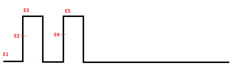
If you have an external trigger with two quick, successive signals and nothing following it would be as follows:

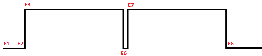
However, if your exposure time was longer than the trigger pulses it would be:

With a trigger latch created by logic blocks your exposure would be:

Step 1—Determine your Inputs
For this example, there are three inputs: Trigger Pulse (Line 0), Frame Trigger Wait (FTW), and Exposure Start (ES).
Input—Trigger Pulse
Trigger pulse refers to the input trigger. There are five possible events in this signal.
For this input, only the rising edge events are needed so the trigger pulse occurs on E2 and E4.
| Event | Trigger Pulse Rising Edge |
|---|---|
| E1 | 0 |
| E2 | 1 |
| E3 | 0 |
| E4 | 1 |
| E5 | 0 |
Input—Frame Trigger Wait
FTW refers to when the camera is ready to be triggered. It's 0 if exposing/reading out and 1 if ready for trigger. There are six possible events in this input.
| Event | FTW |
|---|---|
| E1 | 1 |
| E2 | 1 |
| E3 | 0 |
| E6 | 1 |
| E7 | 0 |
| E8 | 1 |
When trigger pulse and frame trigger wait are combined there are eight events.
| Event | Trigger Pulse | FTW |
|---|---|---|
| E1 | 0 | 1 |
| E2 | 1 | 1 |
| E3 | 0 | 0 |
| E4 | 1 | 0 |
| E5 | 0 | 0 |
| E6 | 0 | 1 |
| E7 | 0 | 0 |
| E8 | 0 | 1 |
The goal is to trigger the camera at events E2 (the first external trigger) and E6 (when the camera is next ready to be triggered). This is the Logic Block 0 output.
| Event | Trigger Pulse |
FTW | LB0 Output |
|---|---|---|---|
| E1 | 0 | 1 | |
| E2 | 1 | 1 | 1 |
| E3 | 0 | 0 | |
| E4 | 1 | 0 | |
| E5 | 0 | 0 | |
| E6 | 0 | 1 | 1 |
| E7 | 0 | 0 | |
| E8 | 0 | 1 |
At this point E6 triggers the camera because E4's output is 1 and E5 and E6 copy the previous output.
| Event | Trigger Pulse |
FTW | LB0 Output |
|---|---|---|---|
| E1 | 0 | 1 | |
| E2 | 1 | 1 | 1 |
| E3 | 0 | 0 | |
| E4 | 1 | 0 | 1 |
| E5 | 0 | 0 | Q (previous) |
| E6 | 0 | 1 | Q (previous) |
| E7 | 0 | 0 | |
| E8 | 0 | 1 |
However, in this scenario the camera would not stop triggering.
Once an output is set for a given set of inputs it cannot be changed. Because E5 (0,0) was given the output of Q (previous), then E3/E7 (0,0) must also be Q (previous). And because E6 (0,1) was given the output of Q (previous), then E1/E8 (0,1) must also be Q (previous). Therefore there is not a point when LB0 wouldn't trigger.
| Event | Trigger Pulse |
FTW | LB0 Output |
|---|---|---|---|
| E1 | 0 | 1 | Q (previous) |
| E2 | 1 | 1 | 1 |
| E3 | 0 | 0 | Q (previous) |
| E4 | 1 | 0 | 1 |
| E5 | 0 | 0 | Q (previous) |
| E6 | 0 | 1 | Q (previous) |
| E7 | 0 | 0 | Q (previous) |
| E8 | 0 | 1 | Q (previous) |
Input—Exposure Start
By using a third input, Exposure Start (ES), there are two new events: E2.5 and E6.5.
After a trigger pulse (TP=1), if the camera is not exposing (FTW=1), then the camera starts exposing (ES=1). This ensures subsequent events are 0 if they rely on previous events [Q (previous)].
| Event | Exposure Start (ES) |
Trigger Pulse (TP) |
FTW | LB0 Output |
|---|---|---|---|---|
| E1 | 0 | 0 | 1 | Q (previous) |
| E2 | 0 | 1 | 1 | 1 |
| E2.5 | 1 | 0 | 0 | 0 |
| E3 | 0 | 0 | 0 | Q (previous) |
| E4 | 0 | 1 | 0 | 1 |
| E5 | 0 | 0 | 0 | Q (previous) |
| E6 | 0 | 0 | 1 | Q (previous) |
| E6.5 | 1 | 0 | 0 | 0 |
| E7 | 0 | 0 | 0 | Q (previous) |
| E8 | 0 | 0 | 1 | Q (previous) |
Step 2—Determine your Input Activation Types
In this example, the activation type for Exposure Start can be Rising Edge or Level High, as it occurs only briefly. Trigger Pulse (Line 0) has to Rising Edge as the trigger pulse could potentially be set to stay higher than normal. Frame Trigger Wait should be Level High as the cameras should be triggered as long as it is ready, not just the instant it becomes ready.
Step 3—Determine your LB0 Output
The addition of the Exposure Start input ensures subsequent events are 0 if they rely on previous events [Q(previous)].
| Event | Exposure Start (ES) | Trigger Pulse (TP) |
FTW | LB0 Output |
|---|---|---|---|---|
| E1 | 0 | 0 | 1 | Q (previous) |
| E2 | 0 | 1 | 1 | 1 |
| E2.5 | 1 | 0 | 0 | 0 |
| E3 | 0 | 0 | 0 | Q (previous) |
| E4 | 0 | 1 | 0 | 1 |
| E5 | 0 | 0 | 0 | Q (previous) |
| E6 | 0 | 0 | 1 | Q (previous) |
| E6.5 | 1 | 0 | 0 | 0 |
| E7 | 0 | 0 | 0 | Q (previous) |
| E8 | 0 | 0 | 1 | Q (previous) |
Step 4—Determine your Value LUT and Enable LUT
To determine the Value LUT and Enable LUT begin with the standard logic block setup. The standard table always begins with row 0 inputs at 0,0,0 and ends with row 7 inputs at 1,1,1.
| Row | Exposure Start (ES) | Trigger Pulse (TP) |
FTW | Value LUT |
Enable LUT |
LB0 Output |
|---|---|---|---|---|---|---|
| 0 | 0 | 0 | 0 | |||
| 1 | 0 | 0 | 1 | |||
| 2 | 0 | 1 | 0 | |||
| 3 | 0 | 1 | 1 | |||
| 4 | 1 | 0 | 0 | |||
| 5 | 1 | 0 | 1 | |||
| 6 | 1 | 1 | 0 | |||
| 7 | 1 | 1 | 1 |
Based on the event table from step 3, rows 0 through 4 represent 5 events that occur in this example. Rows 5 and 7 can never occur as the camera cannot be ready to be triggered and exposure starting at the same time. Row 6 is unlikely to happen (Trigger Pulse at the same time as Exposure Start), but make it a 1 so that a second exposure occurs.
| Row | Exposure Start (ES) | Trigger Pulse (TP) |
FTW | Value LUT |
Enable LUT |
LB0 Output |
|---|---|---|---|---|---|---|
| 0 | 0 | 0 | 0 | Q (previous) | ||
| 1 | 0 | 0 | 1 | Q (previous) | ||
| 2 | 0 | 1 | 0 | 1 | ||
| 3 | 0 | 1 | 1 | 1 | ||
| 4 | 1 | 0 | 0 | 0 | ||
| 5 | 1 | 0 | 1 | 0 | ||
| 6 | 1 | 1 | 0 | 1 | ||
| 7 | 1 | 1 | 1 | 0 |
Use the output table to determine the Value LUT and Enable LUT values.
| D | EN | Q (next) |
|---|---|---|
| 0 | 0 | Q (previous) |
| 0 | 1 | 0 |
| 1 | 0 | Q (previous) |
| 1 | 1 | 1 |