Troubleshooting Image Consistency Errors
Download PDF - Image-Consistency-Errors
Preparing for Use
Before you use your camera, we recommend that you are aware of the following resources available from the our downloads page:
Getting Started Manual for the camera—provides information on installing components and software needed to run the camera.
Technical Reference for the camera—provides information on the camera’s specifications, features and operations, as well as imaging and acquisition controls.
Firmware updates—ensure you are using the most up-to-date firmware for the camera to take advantage of improvements and fixes.
Tech Insights—Subscribe to our monthly email updates containing information on new knowledge base articles, new firmware and software releases, and Product Change Notices (PCN).
Image Consistency Errors
Image consistency errors refer to a range of messages sent by the driver when an image is missing packets or when the camera is otherwise unsuccessful at transmitting image data to the CPU.
How Errors are Reported
SpinView reports image consistency errors in the Log Viewer window, by default found on the bottom of the application.
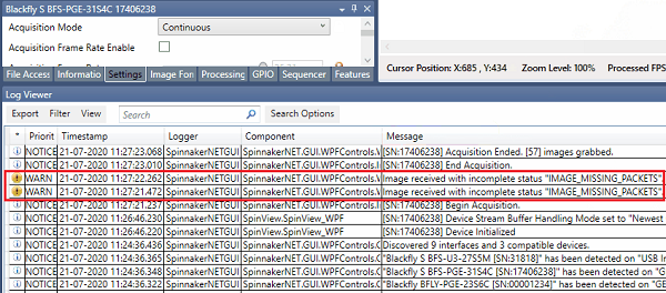
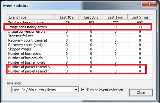
FlyCap2 reports image consistency errors in the GUI Event Statistics Window as shown here. The viewer does not see images with errors, such as torn images, because FlyCapture discards torn images. Other software packages, such as NI-MAX, display torn images when packets are missing.
Causes of Image Consistency Errors
Image consistency errors have a variety of causes, and the user may have to address more than one cause to correct the errors. This table is a summary of the most common causes of errors and their possible solutions. Additional details of possible solutions are given in later sections.
| Cause of Error | Possible Solutions |
| The GigE filter driver is not installed | Install filter driver or update driver. |
| The jumbo packet is not enabled (or is not supported) by the network adaptor. |
enable the jumbo packet option within network card settings, and set camera packet size to the same value (usually 9000). |
| Packet resend is not turned on. | Turn on packet resend option. |
| Packet delay/DeviceLinkThroughputLimit are not tuned. | Set packet delay to be as large as possible while still sending the complete frame. This is most easily done by setting DeviceLinkThroughputLimit to the maximum available bandwidth for that camera, which will automatically configure packet delay. See below |
| Too many dropped packets for packet resend to manage. |
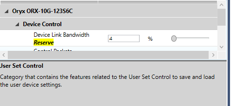
Reduce bandwidth used for streaming to allow room for resend packets to send. Either reduce DeviceLinkThroughputLimit, or configure a percentage of reserve bandwidth via DeviceLinkBandwidthReserve:
|
| DPC latency rate is too high, or CPU Kernel-Time load reaches 100%. |
Review the number of tasks being performed and the overall demand on the CPU. Move high intensity applications off the core handling NDIS.sys. Reduce load to that core as much as possible On certain Network Interface Cards(NIC), enabling and configuring RSS may help distribute load. CPU may need to be upgraded, or load-heavy processes like image conversion or image processing may have to be deferred/done on a separate system. |
| Interrupt Moderation Rate is not enabled, or has an incorrect setting. | Turn on the Interrupt Moderation Rate and set it to the most rigorous setting; this will allow the network stack (Windows) to group more packets together before processing, and reduce CPU load |
| Number of receive buffers is set too low. | Increase the value for receiver buffers to the maximum (usually 2048). |
| Lost data packets when streaming in Linux. | Increase packet delay time or increase the amount of memory for receive buffers. |
| Network card cannot handle streaming load |
Distribute packet transmission evenly within the camera frametime by increasing packet-delay (time-between-packet-transmission) Configure network adapter settings:
|
Solutions for Image Consistency Errors
The use of jumbo packet (or jumbo frames) enabled network adapter cards results in fewer image consistency errors. Larger packets result in less overhead on the host CPU. Typically, network drivers split data larger than 1500 bytes into multiple packets. However, the GigE Vision standard allows packet sizes of up to 9014 bytes. These large packets, also called jumbo packets, allow the camera to more efficiently transfer data across the network.
Using jumbo packets results in fewer packets per frame of image, which means there are fewer interruptions for the host and the host is less likely to drop data, resulting in image consistency errors.
Both SpinView and FlyCap2 does not prompt the user to enable Jumbo packet but some third-party software, such as NI-MAX, sends an error message prompting the user to enable jumbo packets when errors occur that may be a result of this option being disabled.

To enable jumbo packets:
- From the Start Menu, open the Control Panel.
- Click on Network and Internet, then click on Network and Sharing Center.
- From the menu on the left side of the window, click Change adaptor settings.
- Right-click on the NIC you want to enable for jumbo packets.
- Select Properties and click Configure.
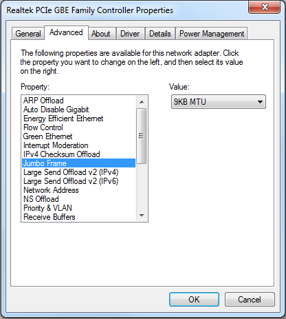
- From the Advanced tab, under Property, select Jumbo frame and Value.
Tuning for Low Latency Image Events
Some machines may encounter latency issues with image events being delayed or arriving with varying timing when RSS and Interrupt Moderation is enabled. If this is true, consider disabling RSS and Interrupt moderation, which have been observed to create timing issues in image event arrival times.
In Short:
For Low Bandwidth, performance driven streaming (accurate image events):
- Disable RSS
Disable interrupt moderation
For High Bandwidth, reliability driven streaming (no packet drops):
- Enable RSS
Enable interrupt moderation
Packet Resend
The Windows network stack Packets are made available to the filter driver for processing (NDIS.sys). When the filter driver detects a gap in the packet ID of the incoming packets, a packet resend request is sent out to the camera to recover the missing packets. If the missing packets are still available in the camera's internal buffer, the packets are retransmitted to the host.
Note that if the camera is already streaming at, or close to, the maximum bandwidth available on the connection, packet resends may overwhelm the available bandwidth and cause subsequent image transmissions to be delayed.
On a connection with known issues in stream reliability, consider lowering the camera bandwidth (throughput) in anticipation of resend packets being transmitted. This can be done by either reserving some bandwidth for packet resends (DeviceLinkBandwidthReserve), or setting a lower value in DeviceLinkThroughputLimit. (Note that DeviceLinkThroughputLimit modifies Packet Delay, and vice versa. It is recommended to lower DeviceLinkThroughputLimit and allow the camera to automatically choose a GevSCPD[Packet Delay] value.)
The filter driver will resend up to GevMaximumNumberResendRequests gaps in the image, per image received. GevPacketResendTimeout provides a worst-case scenario timeout for returning an image buffer.
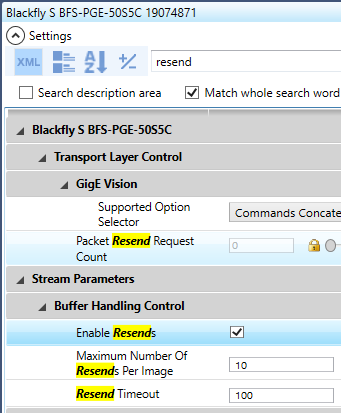
SpinView has packet resend turned on by default (controlled by the "Enable Resends" node):
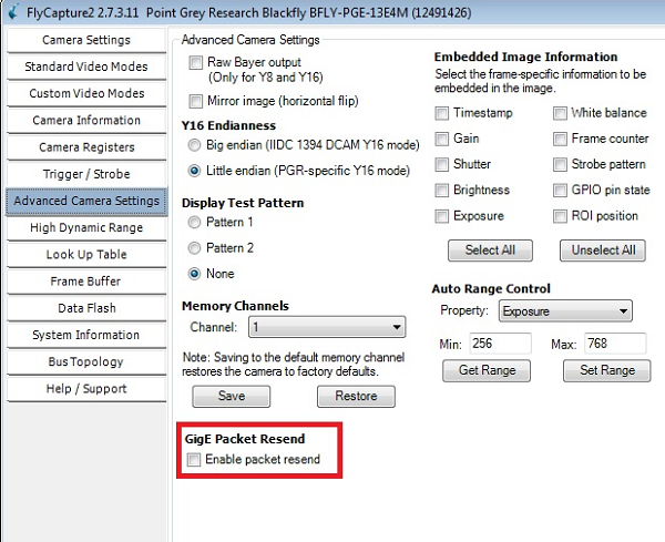
FlyCap2 can have packet resend enabled in the camera control dialog window, Advanced Camera Settings tab.
Kernel Time Usage Reaches 100%
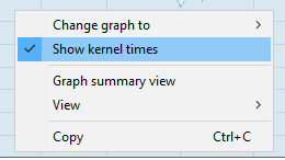
The CPU Core processing networking traffic reaches 100% kernel time utilisation. To view, in Windows 10 Task Manager (performance tab), have CPU selected, right click on graph and select "show kernel times" (kernel time utilization is shown as the darker shade in the graph).
Provided below is an example graph of what it would like when CPU load spike occurs, that has maxed out kernel time utilisation. When this occurs, the CPU will likely by unable to process one or more of the packets submitted by the network card for processing, resulting in a missed packet.
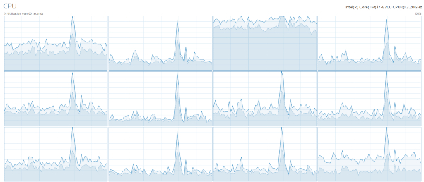
Image Filter Driver
The Windows network copies the network packets from kernel mode to user mode and the user must then make another copy of the image data. Installing an image filter driver eliminates the need for a second copy because the driver copies the image data at the kernel level. This reduces the workload on the CPU and lessens the chance of image consistency errors.
To install Spinnaker's filter driver, in SpinView, right-click on the camera and select filter driver configuration. In the Filter Driver Configuration window, ensure the driver is installed and enabled. Click Refresh if making changes.
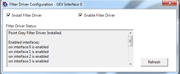
To Install FlyCapture’s filter driver, first install FlyCapture2, then enable the appropriate drivers.
To install FlyCapture:
- Download from our downloads page.
- Select I will use a GigE camera.
To enable the filter driver:
- From the Start Menu → Programs → Use FlyCapture2 → Utilities → GigEConfigurator.
- Click Firewall and Filter Driver Settings.
- Check Install Filter Driver and Enable Filter Driver.
Understanding Packet Delay, Device Link Throughput, and camera framerate
Packet delay controls the delay between data packets trasnmitted out of the camera.
It is generally recommend to set packet delay to as large as possible while maintaining the desired framerate. This spreads out network load as much as possible on the system and minimizes chances of missing packets due to system load.
This is particularly important in multi-camera systems, so as to average out the load on switches and network adapters as much as possible. Lowering the packet delay necessarily will increase the chance of creating large bursts of network traffic, which may cause data to be lost. See "Common scenarios and how you can configure Delay/Throughput for each" below to pick the best packet delay value for common scenarios. Setting packet delay too high will cause camera to stream slowly, or shift data packets completely outside of the available transmission time.
DeviceLinkThroughputLimit reports the maximum throughput possible on the system given the current packet delay setting. The camera frame rate will be set to the largest possible value, and assumes no downtime between data transmission. To make sure that the user configures the framerate, enable the AcquisitionFrameRateEnable node.
Therefore, packet delay is inversely related, and functionally equivalent, to changing the DeviceLinkThroughputLimit on the device. Changing one will affect the other node on the camera, and vice versa.
Note: When programming cameras, only set one of Packet Delay or DeviceLinkThroughputLimit, as setting one automatically sets the other as well. Setting both values will void one of the two settings unless they are mathematically the same.
The relationship between these settings are:
(Image size/Packet Size) + 2 (Leader and Trailer packets) = Packets per image
DeviceThroughput/(PacketsPerImage*PacketDelay) = Maximum camera framerate.
Common scenarios and how you can configure Delay/Throughput for each:
Packet delay at maximum camera framerate:
- Set packet delay to 0. Camera will auto-set to highest framerate.
- Read DeviceLinkCurrentThroughput. This is the bandwidth required by the camera to stream maximum frame rate.
- DeviceLinkThroughputLimit = DeviceLinkCurrentThroughput . This will prompt camera to auto-calculate maximum packet delay for the current throughput.
Packet delay for a specific framerate.
- Calculate the effective throughput required based on image size, image format, and frame rate, and enter the value directly into DeviceLinkThroughputLimit OR
- Reduce DeviceLinkThroughputLimit and check camera framerate, repeating until desired framerate is set by the camera OR
- Increase packet delay, checking camera framerate until desired framerate is set by the camera
Packet Delay for multicamera streaming
- Calculate the maximum allowable throughput per camera and enter it into the Throughput limit node.
- Observe the framerate the camera as adjusted to. If the desired framerate is lower than what the camera is auto-configured to, lower DeviceLinkThroughputLimit value (or increase packet delay) until the desired framerate is met.
- Note: If packet delay is left at 0 while using multiple cameras through a switch into the same network card, all connected cameras may begin transmission at the same time, causing a 'burst' of high-load on the network, which increases the chance of losing data over the network due to the inability of the switch/network stack to handle the influx of packets.
Changing Packet Size and Device link throughput limit in SpinView and FlyCap
In SpinView, Packet Size and Packet Delay can be found by entering "packet" in the feature tab's search bar.
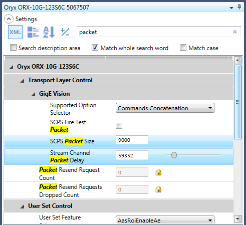
Furthermore, rather than directly modifying packet delay, it may be more intuitive to change the device link throughput limit, which allows you to control the maximum bytes-per-second the camera is allowed to stream at. Reducing this value reduces the cameras max framerate, and automatically changes the packet delay as well.
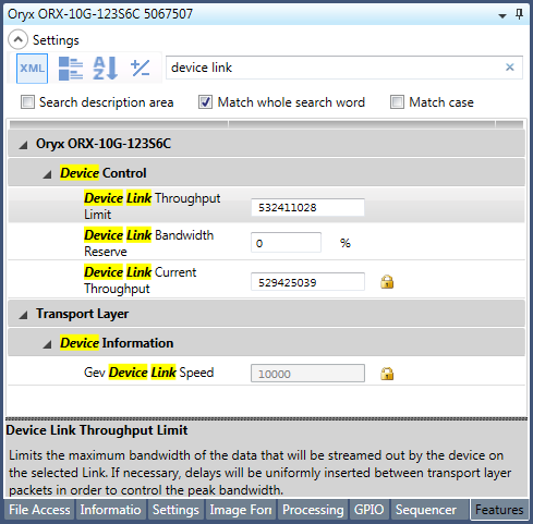
Set the packet size to the maximum (9 k with jumbo packets enabled) and choose your device link throughput limit that still allows the required frame rate without errors. Adjust the packet size and delay time as required to minimize errors or dropped packets.
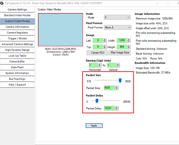
In FlyCap2, packet size and delay can be controlled in the custom video modes tab in the camera control dialog window.
Dropped Packets and Hardware Incompatibilities
Incompatible hardware may cause too many dropped packets for packet resend to fix the error. Try a different Ethernet cable or network adapter. Check the bandwidth capabilities of the network adapter. A typical network adapter handles 1 Gb/s but some older adapters can only handle 100 Mb/s (10x slower). If the adapter can’t handle the amount of image data being transferred, the result is a large number of dropped packets.
A multi-camera set-up connected through a switch to a single network port may transfer more data than the network can process, resulting in dropped packets; again, a single gigabit connection can only handle a maximum of approximately 125MB/s, with most gige cameras being able to achieve that bandwidth, or near it, with one camera. To lower the bandwidth transferred to the network adapter, increase the packet delay/reduce the device link throughput limit, or the image resolution on one or more cameras. Make sure that you are sending less than the maximum amount of data for your network adapter (see above).
Even if the combined throughput of a multi-camera setup is less than the maximum bandwidth of your network adapter, the use of multiple network adapters may help utilize more system resources to avoid packet loss. For example, two cameras streaming at 5Gb/s connected through a switch to a single 10Gb network adapter may experience higher system load and a higher chance of dropped packets than if the same cameras are each directly connected to a distinct 10Gb network adapter. See above for maximizing packet delay to reduce possible high traffic on the switch.
Deferred Procedure Calls (DPC) Latency
A DPC is a process that defers tasks with a low priority in order to immediately process high-priority tasks. A high DPC latency indicates that that system is experiencing many delays as a result of high bandwidth demand and image packet data is not being handled at a rate fast enough to avoid dropped packets and image consistency errors.
When the PC performs side tasks such as opening up an image stream or playing media while the camera is running on the system, these side tasks can generate a number of DPCs. If the DPCs all run on the same core and at the same priority as the image data (grabbing and streaming), it causes problems trying to handle all the interrupts at the same time. Although the DPCs may not be running on the same core, it is likely that any DPC created by a network driver is running on the same core. DPCs created elsewhere (USB, graphics) are likely to run elsewhere on a multi-core system.
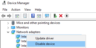
In addition, latency issues may be caused by drivers other than network drivers, such as graphics drivers, wi-fi or usb drivers. For best performance, update all adapter drivers and ensure they are kept up-to-date, and disable any interfaces that will not be used during streaming.
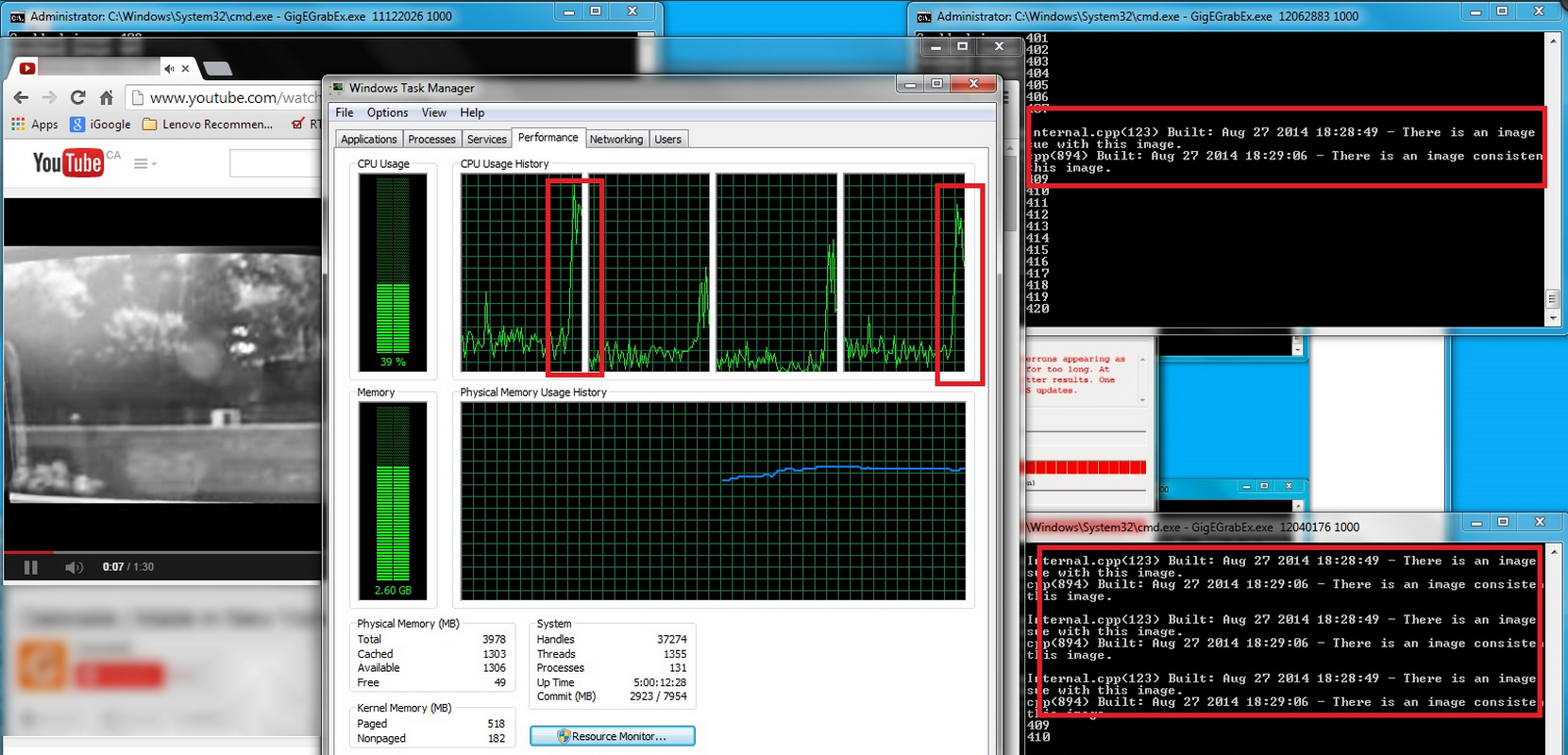
The screen capture below shows a high DPC latency while a media file is being played on YouTube. Note the spike in CPU usage and the corresponding errors. As the CPU usage stabilizes, the image consistency errors disappear, even though the media is still playing. This shows how the initial creation of DPCs affects the rate of image grabbing from the camera. As the DPCs are handled, the image grabbing rate recovers, even while the video continues to play. To reduce the latency, do not run too many tasks simultaneously. Resources diverted from the camera to other tasks reduces the amount of resources available for image capture.
Interrupt Moderation Rate
This solution is suggested for advanced users.
Interrupt moderation allows the adapter to moderate the interrupts. When a packet arrives, the adapter generates an interrupt, which allows the driver to handle the packet. At greater linkspeeds, more interrupts are created, increasing the demand on the CPU. Too many interrupts result in poor system performance. When you enable Interrupt Moderation, the interrupt rate is lower, and the system performance improves.
Interrupt Moderation Rate sets the rate at which the controller moderates or delays the generation of interrupts, optimizing network throughput and CPU use. The Adaptive setting adjusts the interrupt rates dynamically, depending on traffic type and network usage. Choosing a different setting may improve network and system performance in certain configurations. If the moderation rate is high, the amount of interrupts will be suppressed. The less often the interrupt happens, the lower the CPU load. However, the less often the interrupt happens, the more likely the ACK respond from the host will be slow, resulting in the host responding to a request or accepting an image packet more slowly. Adjust the moderation rate based on the system, camera and data rate of your current configuration.

Receive Buffers
This solution is suggested for advanced users.
Receive buffers are used by the adaptor when copying image data to the system’s memory. Increasing the number of the buffers can enhance receive performance, but also uses more memory. Set the number of the receive buffers based on the camera configuration.
Receive Side Scaling
Network adapters support configuration of Receive side scaling, which by design spreads DPC load to multiple processors instead of using a single processor. The powershell commands "Get-NetAdapterRSS, Set-NetAdapterRSS" can be used to configure specific load distributions. On some systems, RSS settings do not seem to have noticible impact until the primary processor load is maxed, at which point additional load is scheduled to other processors. This may not be enough to prevent packet drops upon the primary core reaching 100% kernel time utilization.
