Calibrating to Reduce Horizontal Line Artifact
Download PDF - Calibrating_Horizontal_Line_Artifact
Introduction
For cameras with the IMX036 sensor, an internal characteristic of the sensor may cause a horizontal stripe pattern under certain conditions. The stripe pattern manifests itself as alternating light and dark pixel rows. The stripes may appear to alternate light and dark vertically as well, creating a grid-like or "screen door" pattern.
The horizontal stripes appear to be an image with dark/bright rows alternating in flat regions. Dark/bright columns appear to be an image with columns alternating in flat regions. The patterns look like:
|
|
Examples
The artifact is more noticeable at image boundaries than at image centers. The sample images below show the image corner and center for the same scene under different F numbers. The images have 10x zooming applied.
|
F1.2 Corner |
F1.2 Center |
 |
 |
|
F2.0 Corner |
F2.0 Center |
 |
 |
|
F2.8 Corner |
F2.8 Center |
 |
 |
|
F4.0 Corner |
F4.0 Center |
 |
 |
|
F5.6 Corner |
F5.6 Center |
 |
 |
Causes of the Artifact
The artifact is caused by the physical structure of the pixels, which causes a noticeable imbalance between Gr (green pixel adjacent to red) and Gb (green pixel adjacent to blue). It is affected by the back focal length and the aperture opening. In general, a longer back focal length and a smaller aperture (larger F number) will reduce the artifact.
Recommendations:
- An F number of 2.8 and larger
- Back focal length of -100 mm ~ infinite or -30 mm ~ infinite for color cameras
Calibrating for the Artifact
|
|
The following section is meant for expert users only. |

To correct the imbalance between adjacent rows, one can multiply one row by a ratio to bring it to the same intensity as the other row. The ratio can be obtained through a calibration process. The calibration is based on the fact that the ratio between two adjacent rows has a linear relationship with the pixel distance to the optical center.

To calibrate the camera, one will need to create a relatively flat-field scene. The calibration needs the following components:
- The camera
- A lens that will be used in application
- A desired F-number of the lens that will be used in application
- A relatively flat-field
Step 1: Attach the lens with the desired F# to the camera, and point the camera to the flat- field. Focus the lens, and then adjust it to be slightly out of focus.
Step 2: Grab a raw Bayer image Iin with the same resolution that you will use when the camera is in operation.
Step 3: Extract the green channel from the Bayer image Iin and generate an image Igrn with only the green components from the original Bayer image. We will refer to this image as the green image Igrn.
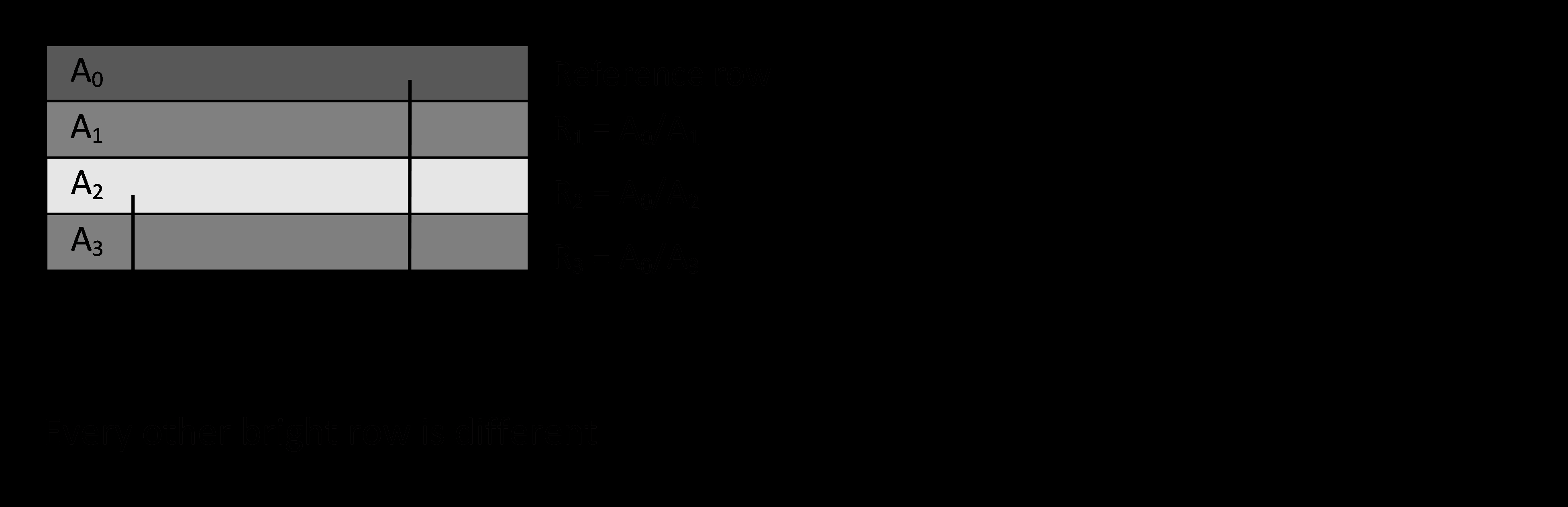
Step 4: Average each row of the green image Igrn and produce a column vector Agrn with each element being the average of one row.
Step 5: Calculate the ratio R of each pair of two adjacent elements in vector Agrn, i.e.,
![]()
where ir is the row index of the column vector. The resulting ratio vector R is half-length of Agrn. When plotting the ratio vector, one should see a linear line.
Example: Calibration Ratios
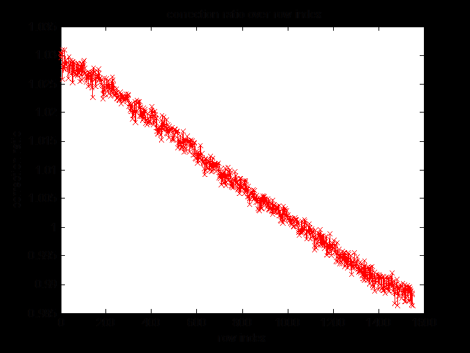
Step 6: Fit a line to the calibration ratios to obtain the line parameters, i.e., slope (S) and offset (O). S and O are the final calibration data that should be stored for correction usage.
|
|
Note that S and O are dependent on lens and F# (aperture), which means a different lens or F# requires a separate calibration. |
Correcting for the Artifact
After obtaining the calibration data (i.e., line slope S and offset O), one can apply correction for the artifact on an input image by using the following equation:
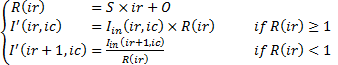
where ir = [1,3,5,..., Rows - 1], ic = [1,2,3,..., Cols], and Rows, Cols are the numbers of rows and columns of the input image (assumed to be even numbers), respectively.
|
Before Correction |
After Correction |
 |
 |
Important Additional Points Regarding Calibration/Correction
- The calibration and correction described above are applied on image rows. However, in practice, the same logic could be applied on image columns to further reduce the artifact, especially under small F# lenses.
- In some cases, especially small F# lenses, instead of obtaining one ratio from every two adjacent rows, one might calculate three ratios from every four adjacent rows. The reason is because adjacent bright rows can be different from each other in some situation.
Example: Use four rows