Configuring Synchronized Capture with Multiple Cameras
What is Synchronized Capture?
Synchronized capture is when two or more cameras are capturing images at the same time; our definition of "the same time" is that the cameras must take start exposing each set of images within microseconds of each other. To achieve this, we show how to use one "primary" camera to trigger one or more "secondary" cameras, using the primary camera's strobe (by default, strobes occur when a camera begins to capture images.). This also ensures that the frame rates of the secondary cameras follow that of the primary camera.
Note: An alternative method of synchronized capture is to have all cameras triggered by an external hardware trigger (for example, a function generator). Any hardware trigger that provides a 3.3 or 5 V square wave TTL signal can trigger the cameras. This application note does not explicitly cover the configuration of an external hardware trigger, but users who want to use an external hardware trigger can act as if the external hardware trigger is the primary camera, and follow the physical layout section mentioned in the article (if a pull-up resistor is implemented, this can be ignored, as external hardware triggers don't need it).
Configuring Synchronized Capture
Note: The pullup resistor values in the examples below are for demonstration purposes only. You may need to use lower resistor values to strengthen the signal.
There are two steps to configuring synchronized capture:
- Create a physical connection between the cameras by linking their GPIO pins.
- Configure inputs and outputs for each camera either with the SDK demo application or with code.
Step 1—Connect the Cameras
The first step is to create a physical link between the cameras. The methods vary depending on the camera used.
Blackfly S (BFS)
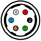
BFS cameras have a 6-pin GPIO. The BFS GPIO has both a non-isolated output and an opto-isolated output. If using the opto-isolated output as in our example below, the primary camera requires a pull-up resistor to strengthen its strobe signal.
| Diagram | Color | Pin | Line | Function | Description |
|---|---|---|---|---|---|
|
|
Green | 1 | 3 | VAUX | Auxiliary Input Voltage (DC) |
| GPI | Non-isolated Input | ||||
| Black | 2 | 0 | OPTOIN | Opto-isolated Input | |
| Red | 3 | 2 | VOUT | Camera Power Output | |
| GPIO | Non-isolated Input/Ouput | ||||
| White | 4 | 1 | OPTOOUT | Opto-isolated Output | |
| Blue | 5 | N/A | Opto GND | Opto-isolated Ground | |
| Brown | 6 | N/A | GND | Camera Power Ground |
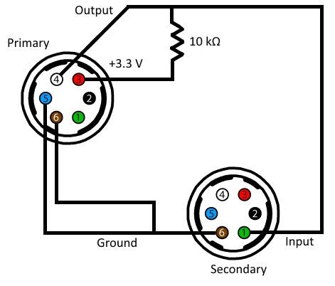
To configure primary and secondary BFS cameras:
- Connect the primary camera's pin 4 (white wire, opto-isolated output) to each secondary camera's pin 1 (green wire, non-isolated input).
- Connect the primary camera's pin 5 (blue wire, opto-isolated ground) to each secondary camera's pin 6 (brown wire, ground).
To configure the pull-up resistor needed to strengthen the signal:
- Connect one end of a 10 kΩ resistor to the primary camera's pin 3 (red wire, 3.3 V output).
- Connect the other end of the resistor to the primary camera's pin 4 (white wire) and to each secondary camera's pin 1 (green wire).
- Connect the primary camera's pin 6 (brown wire) to each secondary camera's pin 6 (brown wire). Note: the secondary camera's pin 6 is already connected to the primary camera's pin 5.
Blackfly (BFLY)
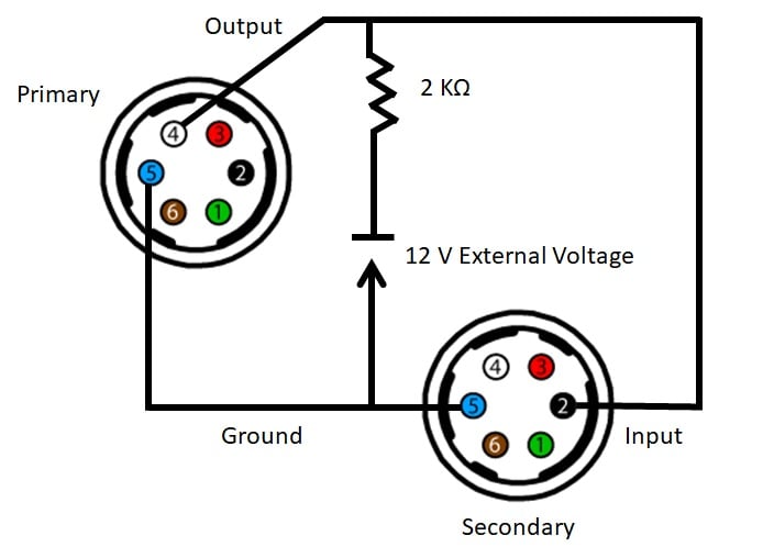
BFLY cameras use a 6-pin GPIO connector. The BFLY GPIO has only opto-isolated output pins, so the primary camera requires a pull-up resistor to strengthen its strobe signal. We recommend using an external pullup voltage of 5 V or higher instead of the the camera's 3.3 V output due to component tolerances.
| Diagram | Color | Pin | Function | Description |
|---|---|---|---|---|
|
|
Green |
1 |
VEXT | +12 V DC Camera Power |
| Black |
2 |
I0 | Opto-isolated input (GPIO 0) | |
| Red |
3 |
NC / +3.3 V | +3.3 V output. Current 120 mA (nominal). Firmware enabled (OUTPUT_VOLTAGE_ENABLE: 19D0h) |
|
| White |
4 |
O1 | Opto-isolated output (GPIO 1) | |
| Blue |
5 |
OPTO_GND | Ground for opto-isolated I/O, not connected to camera ground | |
| Brown |
6 |
GND | DC camera power ground |
To configure primary and secondary BFLY cameras:
- Connect the primary camera's pin 4 (white wire, opto-isolated output) to each secondary camera's pin 2 (black wire, opto-isolated input).
- Connect the primary camera's pin 5 (blue wire, opto-ground) to each secondary camera's pin 5 (blue wire, opto-ground).
To configure the pull-up resistor needed to strengthen the signal:
- Connect one end of a 2 KΩ resistor to an external voltage of 5 V or greater.
- Connect the other end of the resistor to the primary camera's pin 4 (white wire) and to each secondary camera's pin 2 (black wire).
- Connect the primary camera's pin 6 (brown wire) to each camera's pin 5 (blue wire). Note: the secondary camera's pin 5 is already connected to the primary camera's pin 5.
- Connect the external power supply's ground to the already connected ground pins (blue wire).
Chameleon 3 (CM3)
CM3 uses a 9-pin GPIO. It has two non-opto input/output pins that can be used as either input or output. Non-opto pins do not need a pull-up resistor combination to strength the strobe signal. This example uses the non-opto pins.
| Diagram | Color | Pin | Function | Description |
|---|---|---|---|---|
 |
Red | 1 | VEXT | Allows the camera to be powered externally 5 - 24 VDC |
| Black | 2 | GND | Ground for Input/Output, VEXT, +3.3 V pins | |
| White | 3 | +3.3 V | Power external circuitry fused at 150 mA maximum | |
| Green | 4 | GPIO3 / Line3 | Input/Output | |
| Purple | 5 | GPIO2 / Line2 | Input/Output | |
| Black | 6 | GND | Ground for Input/Output, VEXT, +3.3 V pins | |
| Brown | 7 | OPTO_GND | Ground for opto-isolated IO pins | |
| Orange | 8 | OPTO_OUT / Line1 | Opto-isolated output | |
| Yellow | 9 | OPTO_IN / Line0 | Opto-isolated input |
To configure primary and secondary CM3 cameras:
- Connect the primary camera's pin 5 (purple wire, output) to each secondary camera's pin 4 (green wire, input).
- Connect the primary camera's pin 6 (black wire, ground) to each secondary camera's pin 6 (black wire, ground).

Flea3 (FL3) and Grasshopper3 (GS3)
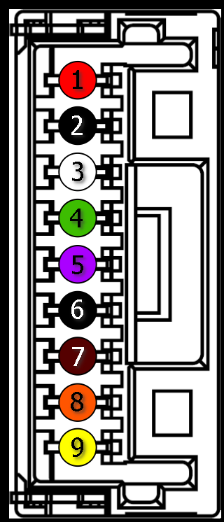
FL3 and GS3 each use an 8- pin GPIO. They have two non-opto input/output pins that can be used as either input or output. Non-opto pins do not need a pull-up resistor combination to strength the strobe signal. This example uses the non-opto pins.
| Diagram | Color | Pin | Function | Description |
|---|---|---|---|---|
 |
Black | 1 | I0 | Opto-isolated input (default Trigger in) |
| White | 2 | O1 | Opto-isolated output | |
| Red | 3 | IO2 | Input/Output/serial transmit (TX) | |
| Green | 4 | IO3 | Input/Output/serial receive (RX) | |
| Brown | 5 | GND | Ground for bi-directional IO, VEXT, +3.3 V pins | |
| Blue | 6 | OPTO_GND | Ground for opto-isolated IO pins | |
| Orange | 7 | VEXT | Allows the camera to be powered externally | |
| Yellow | 8 | +3.3 V | Power external circuitry up to 150 mA |
To configure primary and secondary FL3 or GS3 cameras:
- Connect the primary camera's pin 3 (red wire, output) to each secondary camera's pin 4 (green wire, input).
- Connect the primary camera's pin 5 (brown wire, ground) to each secondary camera's pin 5 (brown wire, ground).
Oryx (ORX)
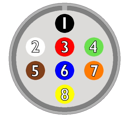
ORX cameras have a 12-pin GPIO. It has two non-opto input/output pins that can be used as either input or output. Non-opto pins do not need a pull-up resistor combination to strength the strobe signal. This example uses the non-opto pins.
| Color | Pin | Line | Function | Description | |
|---|---|---|---|---|---|
 |
Black | 1 | N/A | GND | DC camera power ground |
| White | 2 | N/A | POWER | DC camera power | |
| Red | 3 | Line 1 | GPIO_OPT_OUT1 | Opto-isolated output (GPO1) | |
| Green | 4 | Line 4 | GPIO_OPT_OUT2 | Opto-isolated output (GPO2) | |
| Orange | 5 | Line 0 | GPIO_OPT_IN1 | Opto-isolated input (GPI1) | |
| Blue | 6 | Line 3 | GPIO_OPT_IN2 | Opto-isolated input (GPI2) | |
| White/black stripes | 7 | Line 2 | GPIO_TTL_IO3 | TTL input/output 3* | |
| Red/black stripes | 8 | Line 5 | GPIO_TTL_IO4 | TTL input/output 4* | |
| Green/black stripes | 9 | N/A | GND | DC camera power ground | |
| Orange/black stripes | 10 | N/A | POWER | DC camera power | |
| Blue/black stripes | 11 | Line 6 | 3.3 V OUTPUT | +3.3 V output, current 120 mA (nominal) - firmware enabled | |
| Black/white stripes | 12 | N/A | OPTO_GND | Ground for opto-isolated I/O, not connected to camera ground | |
| *When configured as output line format is open drain, not TTL. Users should attach their own external pull-up resistor. | |||||
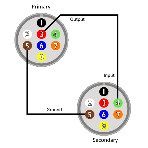
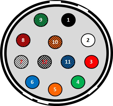
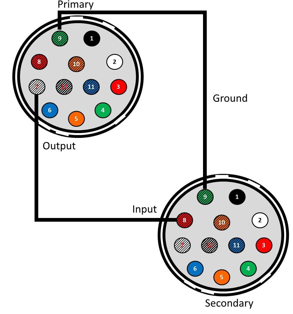
To configure primary and secondary ORX cameras:
- Connect the primary camera's pin 7 (white with black stripes wire, output) to each secondary camera's pin 8 (red with black stripes wire, input).
- Connect the primary camera's pin 9 (green with black stripes wire, ground) to each secondary camera's pin 9 (green with black stripes wire, ground).
Firefly-DL (FFY-DL)
The Firefly DL uses a 6-pin GPIO. It only has non-opto isolated pins that can be used an either input or output. Non-opto pins do not need a pull-up resistor to strengthen the strobe signal.
| Diagram | Color | Pin | Line | Function | Description |
|---|---|---|---|---|---|
|
|
Orange | 1 | Line 0 | GPIO0 | Non-isolated Input/Output TXD(output) for 1.8V UART |
| Black | 2 | Line 1 | GPIO1 | Non-isolated Input/Output RXD(input) for 1.8V UART | |
| White | 3 | Line 2 | GPIO2 | Non-isolated Input/Output | |
| Green | 4 | Line 3 | GPIO3 | Non-isolated Input/Output | |
| Brown | 5 | N/A | GND | Camera Power Ground | |
| Red | 6 | N/A | Vout | Camera Power Output |

To configure primary and secondary FFY-DL cameras:
1. Connect the primary camera's pin 3 (white wire, output) to each secondary camera's pin 4 (green wire, input)
2. Connect the primary camera's pin 5 (brown wire, ground) to each secondary camera's pin 5 (brown wire, ground)

Step 2—Configure the Cameras
After the cameras have been physically connected, use either the SDK's demo program or write code to configure the GPIO lines.
Using SpinView
SpinView is the demo program available with the Spinnaker SDK.
For the primary camera:
- Open SpinView.
- Select the camera.
- On the Features tab, click Digital IO Control.
- Set the output line
- For CM3, FL3, GS3, FFY-DL, and ORX cameras, select Line2 from the Line Selection dropdown, set Line Mode to Output and set Line Source to ExposureActive.
- For BFS cameras, select Line1 from the Line Selection dropdown and set Line Mode to Output.
- For BFS and BFLY cameras enable the 3.3V line
- For BFS cameras from the line selection drop-down select Line2 and check the checkbox for 3.3V Enable.
- For BFLY cameras, set 3.3V Enable to true
- (Optional) Save the settings in a user set:
- Click User Set Control.
- From the User Set Selector drop-down, select User Set 0 or User Set 1.
- Click User Set Save.
- (Optional) From the User Set Default drop-down, select User Set 0 or User Set 1. This will ensure that this userset is loaded when the camera is booted up.
For each secondary camera:
- Open SpinView and select the camera.
- Select the GPIO tab.
- Set the trigger source
- For BFS, CM3, FL3, FFY-DL, and GS3 cameras, from the Trigger Source drop-down, select Line 3.
- For ORX cameras, from the Trigger Source drop-down, select Line 5.
- For BFLY cameras, from the Trigger Source drop-down, select Line 0
- From the Trigger Overlap drop-down, select Read Out.
- From the Trigger Mode drop-down, select On.
- (Optional) Save the settings in a user set:
-
- Click User Set Control.
- From the User Set Selector drop-down, select User Set 0 or User Set 1.
- Click User Set Save.
- (Optional) From the User Set Default drop-down, select User Set 0 or User Set 1. This will ensure that this userset is loaded when the camera is booted up.
To start streaming, select each camera and click Play. ![]()
Using FlyCap2 (BFLY, FL3, GS3, CM3)
FlyCap2 is the demo program available with the FlyCapture2 SDK.
For the primary camera:
- Open FlyCap2, select the camera and click Configure Selected.
- For BFLY camera only, enable the 3.3 V line (red):
- In the Camera Control dialog, select the Camera Registers tab.
- Enter Register 19D0h (OUTPUT_VOLTAGE_ENABLE) and click Read Register.
- Set bit 31 to 1.
- Click Write Register.
- For all cameras, enable the strobe:
- Select the Trigger/Strobe tab.
- For BFLY camera only, enable the strobe for GPIO1.
For all other cameras, enable the strobe for GPIO2.
- Save the settings:
- Select the Advanced Camera Settings tab.
- Select a Memory Channel (either 1 or 2).
- Click Save.
For each secondary camera:
- Open FlyCap2, select the camera and click Configure Selected.
- In the Camera Control dialog, select the Trigger/Strobe tab.
- For BFLY camera only, set the Source to 0.
For all other cameras, set the Source to 3. - Set the Mode to 0 or 14. (Not all models support trigger mode 14.)
- Select Enable/disable trigger.
- Save the settings:
- Select the Advanced Camera Settings tab.
- Select a Memory Channel (either 1 or 2).
- Click Save.
Start Saving Images at the Same Time
Once you have configured the primary and secondary cameras you can start saving synchronized images.
Note: If saving images at high bandwidth, we recommend using a console application instead SpinView or FlyCap2. For details, see Saving Images at High Bandwidth.
For both SpinView and FlyCap2:
- Ensure the primary camera's trigger mode is turned on.
- In the streaming window for the primary camera, click on the recording button.
- Modify the recording settings as necessary.
- Click the Start Recording button.
- Keep the recording window open.
- Repeat steps 1 through 5 for the secondary camera.
- Turn off trigger mode for the primary camera. This starts capture for both cameras.
Using Custom Code
Both the Spinnaker SDK and the FlyCapture2 SDK come with example code. Elements of these two code examples can be combined to configure multiple cameras.
| SDK | Examples | Location |
|---|---|---|
| Spinnaker SDK | AcquisitionMultipleCamera Trigger |
\src\ of the SDK directory Example: C:\Program Files\Point Grey Research\Spinnaker\src |
| FlyCapture2 SDK | MultipleCameraEx AsyncTriggerEx |
\src\ of the SDK directory Example: C:\Program Files\Point Grey Research\FlyCapture2\src |
In the example configurations above, FL3, GS3, and CM3 use switchable input/output GPIO pins for their strobe outputs. The strobe must be turned on when using these cameras for synchronized capture. To turn on the strobe, create an instance of the StrobeControl struct using the following code:
StrobeControl strobe;
strobe.source = 2;
error = cam.GetStrobe(&strobe);
strobe.onOff = true;
error = cam.SetStrobe(&strobe);
Troubleshooting
Secondary camera captures images at half the frame rate of the primary camera
Cause: The secondary camera isn't using overlapping triggering
Solution: On the secondary camera, switch to using Trigger Overlap as described above. Not all camera models support Trigger Overlap (Trigger Mode 14). To determine if it is supported, consult the Technical Reference for your camera, available from the camera's support page.
For more information on trigger modes and differences between overlapped and non-overlapped triggering, see the following knowledge base articles:
- Maximum framerate possible in asynchronous (trigger) mode
- What external trigger modes are suported by my camera?
Secondary camera captures images at a very slow frame rate
Cause: The camera's exposure (shutter) value is too large.
Solution: Exposure (shutter) time can be adjusted.
- In SpinView—On the Settings tab
- In FlyCap2—On the Camera Settings tab of the Camera Control dialog.
I can't properly trigger more than one secondary camera
Cause: the physical setups shown above have been tested with only one secondary camera; we do not guarantee they will work for multiple secondary cameras.
Solution: Modify the pull up resistor setup to accommodate the additional cameras.