Enhancing USB 3.1 Cameras Reliability with Frame Buffer
What's inside:
-
- Reasons for image corruption and image loss
- Preventing image corruption and image loss
- Frame buffer explained
- Frame buffer performance
Enhancing_USB 3.0_Cameras_Reliability_with_Frame_Buffer.pdf
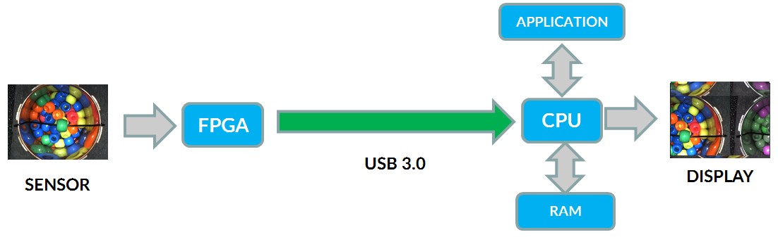
Image transmission reliability is often a key factor to consider when building a machine vision system. Corrupted or lost image data often hinders system performance and decreases efficiency. A frame buffer on board the camera can be used to address these reliability issues.
What causes image corruption or data loss?
Image data can get corrupted or lost for several reasons. A poorly constructed cable or an electrically noisy environment may cause signal degradation leading to image corruption. A host system that is busy doing image processing may be unable to request additional images from the camera, causing the data to overflow on the camera and corrupt the data.
USB 3.1 utilizes Dynamic Memory Access (DMA), where the image data can be transferred from the host controller to the system memory with minimal management from the CPU. Instead of waiting for the transfer to complete, the CPU can now go on with other operations and be interrupted by the DMA controller when the transfer has been completed. However if the image processing software does not process the image data, the host controller runs out of memory buffers to store the new image data. At this point, the host system stops requesting new images from the camera, and the image data start to accumulate on the camera buffer and eventually overflows. When the overflow happens, an existing image may be partially overwritten with the new image, causing an image frame to be corrupt and appear “torn”.
Data overflow causing two images to appear in the same frame and the image to appear “torn”
How do I prevent image corruption or data loss?
USB 3.1 supports several transmission mechanisms including isochronous transfer and bulk transfer. The USB3 Vision committee has chosen to use bulk transfer which guarantees data delivery and has key reliability features such as retransmission and error checking capabilities. Point Grey is further leveraging these improvements in its camera design by equipping each USB 3.1 camera with a frame buffer.
A frame buffer is memory onboard the camera allocated to temporarily store image data before transmission. The image data is organized using a FIFO (first-in, first-out). The buffer typically sits at the end of the imaging processing pipeline, right before the interface controller. With a large frame buffer that stores several images, the camera can retransmit the whole image if necessary or drop the image cleanly without introducing torn images. A frame buffer large enough to store at least one frame can always guarantee the arrival of a single triggered image. The retransmission is managed by the host controller and does not need to be managed by the user.
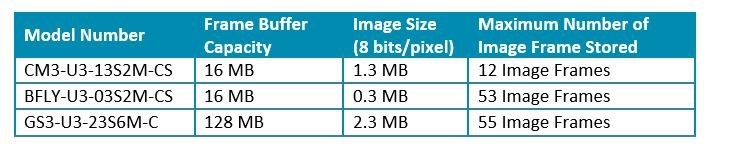
Frame buffer size for Point Grey USB 3.1 cameras
Can the frame buffer impact transmission latency?
Even though the frame buffer improves camera reliability, some users have concerns that data transmission will take longer due to having the extra buffer in the transmission pipeline. To maximize camera reliability without sacrficing camera performance, the data transmission process starts as soon as partial data is received from the image sensor. As long as the host is avaliable to receive the data, the transmission delay is minimized.
In summary, the frame buffer is a safe guard against unexpected events such as the host system being busy and dropping the data. The camera feature is a must have for machine vision cameras being used in mission critical systems. All Point Grey USB 3.1 cameras ship with frame buffers to provide maximum camera reliability.